


Fundamental Operation of Pilot-Operated Safety Relief Valves
In this second of a series, we explore another type of pressure relief valves used in common applications.
#pressure-relief #basics #knowyourvalves
Share
In this second installment of this pressure relief valve fundamentals series, we will discuss another type of pressure relief valve (PRV) called a pilot-operated safety relief valve (POSRV). In the Fall 2023 issue, we covered the fundamental operation of spring-loaded safety relief valves in detail and some of their common applications.
A pilot-operated safety relief valve is a pressure relief valve in which the major relieving device (main valve) is combined with and is controlled by a self-actuated auxiliary pressure relief valve called a pilot valve. Pilot-operated safety relief valves can be flowing or non-flowing, and come in two pilot types – pop action and modulating action. See Figures 1 and 2 for illustrations of these pilot types.
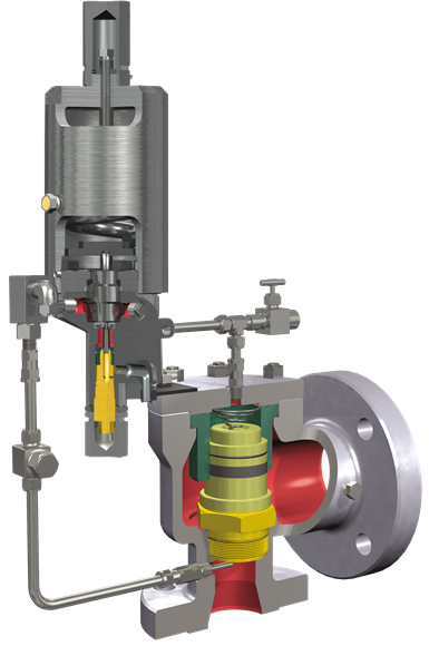
Figure 1: Pop action POSRV.
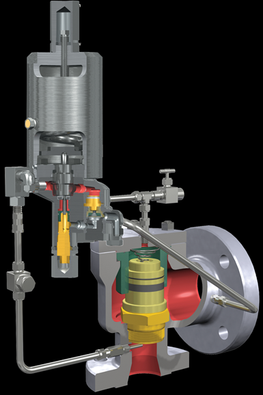
Figure 2: Modulating action POSRV.
Operational Basics of Pilot-Operated Safety Relief Valves
The pilot valve operates by sensing system pressure and using this pressure to control the closing force on the main valve disc. Increasing inlet valve pressure results in increased closing force until the pilot valve opens. Pressure is relieved at a designated set point as process media is allowed to discharge through the main valve.
Pop Action POSRV
Use of the pop pilot configuration will result in a main valve disc “pop” action from the seated position to 100% open. When the overpressure condition is relieved, the main valve disc will reseat due to the increased media pressure directed through the pilot valve to the top of the valve disc (dome).
As shown in Figure 3, system pressure from the main valve inlet is fed to the dome area by the pilot through interconnected tubing. This equalizes the pressure on the top of the disc with inlet pressure on the seating surface (bottom) of the disc. Since the area of the top of the disc is larger than the area of the seating surface, the differential area results in a net downward force keeping the main valve tightly closed.
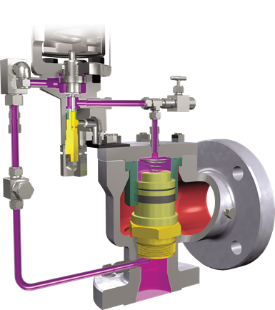
Figure 3: Main valve closed (normal position).
Figure 4 shows that as inlet pressure increases, the pilot piston strokes and seals off the main valve inlet pressure from the dome pressure. The pilot simultaneously opens the vent seal to relieve the dome pressure to atmospheric pressure.
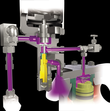
Figure 4: PV valve open (relieving position).
The main valve disc is allowed to lift off the seat as the fluid force overcomes the now removed pressure load above the main valve disc. The valve discharges to relieve system pressure.
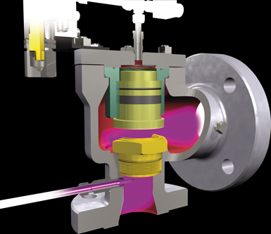
Figure 5: Discharge through the main valve.
When the discharging main valve reduces the inlet pressure to the preset blowdown pressure of the pilot, the pilot piston closes the vent seal. Simultaneously, the inlet seal is reopened in the pilot. The main valve inlet pressure is again allowed to enter the dome above the main valve disc. As the dome pressure equalizes with the inlet pressure, the downward force created by the differential areas of the disc closes the main valve.
Modulating Action POSRV
The modulating pilot operation is very similar to the pop pilot operation with the added ability to hold a percentage of system pressure above the main valve disc, producing a modulating action. Increasing the system pressure results in reduced closing force due to venting through the pilot valve. Pressure relief begins at a designated set point as process media is discharged through the main valve. However, the actual lift of the main valve disc is based on the specific system overpressure condition instead of “popping” instantaneously to the 100 percent open position. This “modulating” action results in improved operating efficiencies through reduced media loss and lower emissions.
Figure 6 illustrates how system pressure from the main valve inlet is fed to the dome area by the pilot through interconnected tubing. This equalizes the pressure on the top of the disc with inlet pressure on the seating surface (bottom) of the disc. Since the area of the top of the disc is larger than the area of the seating surface, the differential area results in a net downward force keeping the main valve tightly closed.
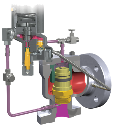
Figure 6: Main valve closed (normal position).
Figure 7 shows that, as inlet pressure increases, the pilot piston strokes and seals off the main valve inlet pressure from the dome pressure. The pilot simultaneously opens the vent seal to relieve the dome pressure to the bottom of the modulator piston. The modulator piston has a differential area with the smaller area being on top. The top of this piston is always subjected to the main valve inlet pressure. When the dome pressure is applied to the bottom of the modulator piston, there is a net upward force. This is due to both pressures being equal (at this point), and the lower area is larger than the upper area. The modulator relieves pressure from the dome to the atmosphere until force from the inlet pressure on top of the modulator piston is sufficient to move it to the closed position. A certain amount of pressure remains in the dome. This pressure is controlled by the differential area in the modulator. Since the dome pressure has not been dropped to atmospheric pressure, the main valve only partially opens at the set point. The modulator piston will remain closed until the main valve disc is forced into higher lift by increasing inlet pressure. As this occurs, the modulator piston may relieve further pressure from the dome as necessary to achieve the required main disc lift within 10% overpressure.
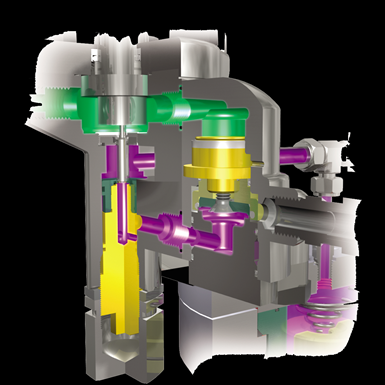
Figure 7: Modulating position.
As the inlet pressure increases further, the net upward force on the main valve increases, allowing the main valve to relieve more pressure. The disc obtains full lift (full capacity) within 10% of set pressure. (See Figure 8.)
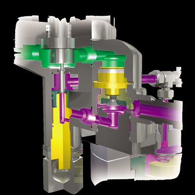
Figure 8: Main valve fully open.
When the discharging valve reduces the inlet pressure to the preset blowdown pressure of the pilot, the pilot piston closes the vent seal. Simultaneously, the inlet seal is reopened in the pilot. The main valve inlet pressure is again allowed to enter the dome above the main valve disc. As the dome pressure equalizes with the inlet pressure, the downward force created by the differential areas of the disc closes the main valve.
Advantages of a Pilot-Operated SRV over a Spring-Loaded SRV
There are many advantages of a pilot-operated SRV over a spring-loaded SRV. Here are a few worth noting:
- Pilot-operated SRVs can achieve seat tightness up to 98% of set pressure for both the main valve and the pilot valve. This ensures zero leakage during normal operating conditions for even the most demanding high-pressure applications.
- Pilot-operated SRVs’ greater seating force make them the ideal solution for higher operating pressure gaps as compared to spring-loaded SRVs. Operating closer to maximum allowable working pressure (MAWP) helps to keep the system running optimally.
- Full-bore pilot-operated SRVs offer much greater capacity compared to standard bore with comparable valve size. This unique offering allows operators to save on valve costs and associated piping investment thanks to reduced piping diameters.
- A modulating action pilot-operated SRV will allow flow for the required capacity of an overpressure event rather than the rated capacity of the valve. This allows users to take advantage of using the system-required flow rate in their line loss calculations rather than the valve-rated flow, thus reducing inlet line losses.
- The field test connection allows operators to functionally test their pilot-operated SRV while the pilot-operated SRV remains in service and continuously protects the system from an unexpected overpressure event.
- The dual pilot option allows users to reduce unplanned outage downtime servicing or replacing one off-line pilot while the other continues protecting their system. This allows service technicians to perform service and repair on a planned schedule.
- The unique design of a pilot-operated SRV connects it to the main valve through interconnected tubing, making it possible to mount different accessories. This includes manual blowdown valves, filters, backflow preventers, pressure differential switches, pilot valve testers, remote pilot mounting, dome assist pilots and others.
Limitations of a Pilot-Operated SRV over a Spring-Loaded SRV
As we've seen, there are some advantages of a pilot-operated SRV over a spring-loaded SRV, but there are also some limitations to consider. Depending on the severity of the dirty service, different types of filters with varying capacities can be installed, and a dome assist option can be installed to isolate the dirty process media from crucial valve components such as the modulator, dome assembly, vent and inlet seals. However, for severe dirty service where clogging of the interconnecting tubing is possible, a pilot-operated SRV might not be the best fit.
A pilot-operated SRV operates by allowing time for system pressure from the main valve inlet to fill the dome area through interconnecting tubing. During plant start-up, when the system pressure has an extremely rapid ramp rate, the dome area may not equalize with the same inlet pressure, resulting in insufficient closing force. Consequently, the system pressure from the main valve inlet will push the main valve disc to lift and start to leak. A spring or alternative pressure can be added in the main valve dome area to close the main valve disc while allowing time for system pressure to ramp. If these remedies are not feasible or economical, a spring-loaded SRV will be the better option in excessive pressure ramp rate applications.
Common Industries and Applications
Pilot-operated SRVs are found in many industries just like spring-loaded SRVs. Common industries using these valves include power generation, refining/petrochemical, chemical, midstream oil and gas, upstream oil and gas and pulp and paper. Some unique applications for pilot-operated SRVs include high-pressure applications, reducing emissions in high operating pressure applications, offshore drilling, and production platforms in deep well applications, and any air/gas, liquid, steam, 2-phase, or multi-case applications.
In the next issue, look for the third article in this series on pressure relief valve basics: safety valves.

Wai Loon Cheong is the valves training leader for Baker Hughes. He has more than 20 years experience, and has worked in a variety of roles at the company.
RELATED CONTENT
-
Understanding Torque for Quarter-Turn Valves
Valve manufacturers publish torques for their products so that actuation and mounting hardware can be properly selected.
-
The Basics of Eccentric Plug Valves
Wastewater systems present many challenges to pumps and valves because the flow can contain grit, solids and debris, depending where in the process the equipment is located.
-
Back to Basics: Globe Valves
There are many applications where the globe valve outshines other designs, so the future is still bright for these long-time favorites of the flow control industry.


 Unloading large gate valve.jpg;maxWidth=214)

