The offshore oil and gas industry began in 1947 when the first well defined as “out of sight of land” was completed at a depth of only about 15 feet (4.6 meters) of water in the Gulf of Mexico. Since that first well was drilled, the offshore sector of oil and gas has become a vital part of where we get these valuable resources. Because of this, exploration and production have moved to deeper and deeper water depths. Nowadays, producible oil and gas are commonly found at depths that are half-a-mile to two-and-a-half miles (1 to 4 kilometers).
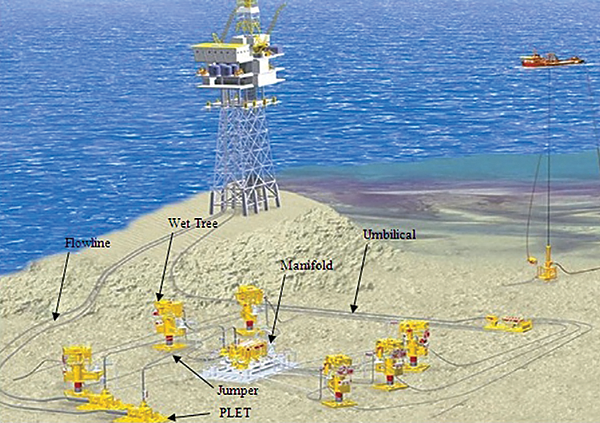
Subsea development includes different types of activities such as exploration, drilling, completion and production. The concept of developing subsea oilfields was born in the early 1970s, using subsea wellheads and Christmas trees, as well as production components and equipment such as manifolds, jumpers and pipelines on the seabed. A key benefit of retrieving oil and gas through subsea oilfields is that these fields improve the production process and allow recovery from reservoirs. The other advantages of subsea operations are that they save costs by reducing space required for topside facilities on a platform or on a floating production storage and offloading vessel (FPSO) and by reducing the large volumes of untreated hydrocarbon that must be transferred from deep subsea depths to the surface.
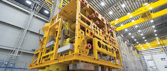
Subsea actuators are located mainly on Christmas trees (Figure 2) and manifolds.
Subsea wells are made up of the downhole well completion components and the subsea trees. Completion is the process of making a well ready for production and injection into the well after drilling. A drilled well is a closed series of piping, fittings and valve assemblies (Christmas trees) that gather the reservoir fluid from the wellhead and direct the produced hydrocarbon to production facilities.
Subsea manifolds are the arrangement of piping, valves, connections, structures and the foundation used in the subsea production system to receive, combine and distribute the hydrocarbon fluid. These manifolds simplify the subsea system by saving the quantity of piping such as pipeline and flow lines that would be needed to transport to other locations for production. Subsea manifolds can be connected to wellheads
Actuation
The actuator is the machine component installed on the top of the industrial valve for automatically or remotely moving and controlling (operating) the valve. The quality of any valve depends on many parameters, including design, material selection, mechanical strength, quality control, manufacturing and more; whereas the performance of the valve is largely dependent on the actuator.
Although all three types of actuators—hydraulic, pneumatic and electrical—are used for industrial valves in other sectors of oil and gas; subsea operations use only hydraulic and electrical actuators.
Subsea actuators are designed and tested mainly through guidelines from the American Petroleum Institute (API) and the International Organization for Standardization (ISO). Each API standard used for subsea valves and actuators has an equivalent ISO standard as follows:
- API Spec.17D, Design and Operation of Subsea Production Systems-Subsea Wellhead and Tree Equipment, identical to ISO 13628-4
- API Spec. 6A, Wellhead and Tree Equipment, identical to ISO 10423.
Several types of actuator designs are used in subsea operations including linear, scotch yoke, and rack and pinion.
Linear actuators are used for subsea gate valves for creating motion in a straight line with linear motion of the stem as well as the closure member (the disk or gate). Linear actuators are spring return with fail-safe closed function in most cases. Linear actuators can be made with double-acting function, but this type of configuration is not common.
Scotch yoke actuators are common for subsea ball valves with quarter-turn or 90-degree motion of the ball for cycling (opening and closing). These actuators can also be made in single-acting or double-acting versions. The single-acting actuator is a spring-return type. It is open in the fail-safe open mode or closed in the fail-safe closed mode with the spring force.
Double-acting actuators normally produce higher force (or torque) compared to single-acting actuators. These are being opened and closed via hydraulic oil pressure. The linear movement of the piston rod is transferred to the yoke and the pin, which transfer the linear movement to rotary movement for 90-degree rotation of the ball valve closure member.
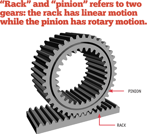
Rack and pinion actuators are common for subsea ball valves with quarter-turn or 90-degree motion of the ball for cycling (opening and closing). “Rack” and “pinion” refers to two gears: the rack has linear motion while the pinion has rotary motion (Figure 6). The linear motion of the rack is achieved through hydraulic force, and it is transferred to the pinion, which moves in rotary and cycles the valve to open or closed positions at 90 degrees.
PRESSURE AND TEMPERATURE RATINGS
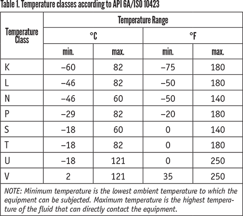
Table 1 provides temperature rating classes in the API 6A/ISO 10423 standard. The minimum rated temperature for the actuator should be selected from the minimum temperature values given in this table unless otherwise required by the end user or in the project specification. The upper working temperature of the actuator should not be less than 149ºF (65ºC) and the maximum upper value of the working temperature could be standardized at that temperature.
OTHER SUBSEA CONSIDERATIONS
Actuated valves are normally supplied with a remotely operated vehicle (ROV) override for the operation of the valves independent of the actuators. ROV override, as a backup for valve actuation, is beneficial in case the actuator fails to function. ROV override interface class is selected based on API 17H/ISO 13628-8, Remotely Operated Vehicle on Subsea Production Systems. ROVs are free-swimming submersible craft used for the operation of the subsea valves and actuators. The vehicle has arms and fingers, which carries a torque tool for the operation of the ROV override.
Subsea valves and actuators must also deal with seawater column external pressure. As a rule of thumb, each 32-foot (10-meter) water depth applies 14 psi (1 bar) pressure to the subsea components. Therefore, an actuator installed at water depths of more than 1.8 miles (3,000 meters) receives about 4,351 psi (300 bar) seawater external pressure. One solution to handling this kind of challenge is to increase the thickness of the actuator, which makes the actuator much heavier. A common alternative is to use a capsule filled with pressurized oil almost equal to seawater external pressure. This is connected to the actuator spring housing, which is called the compensator or compensation system.
ELECTRIC ACTUATION
The other important consideration in talking about subsea actuation is shifting from hydraulic to electric actuators, which is known as a state-of-the-art modification in the subsea sector of the oil and gas industry. This change of actuator operators to electric offers simplification, cost reduction and an environmentally friendly solution. This is because spillage of hydraulic oil is harmful to the environment, potentially damaging marine life and the ecosystem.
Removing the hydraulic oil from the actuator picture also avoids exposing personnel and operators involved in hydraulic actuator manufacturing, testing, inspection, transportation and more.
Because of this, using electrical actuators is considered beneficial from the health, safety and environmental point of view. Other advantages associated with using electrical actuators can include response time, reliability, efficiency and functionality of the subsea system.
No matter the type, however, knowing how they operate and what challenges they face under the sea can help those who specify and put into place the equipment find the right solution for a project.
KARAN SOTOODEH is senior/lead engineer, valves and actuators for Baker Hughes. He can be reached at karan_sqi@yahoo.com.
References
- Bai, Y. & Bai, Q. (2012). Subsea engineering handbook. 1st edition. Atlanta, GA, USA: Elsevier.
- Sotoodeh, K. (2019). A review on subsea process and valve technology. Journal of marine systems and technology. 14, pp.210-219. https://doi.org/10.1007/s40868-019-00061-4
- Sotoodeh, K. (2019). Actuator sizing and selection. Springer Nature Applied Science, Springer Switzerland. 1, 1207. https://doi.org/10.1007/s42452-019-1248-z
RELATED CONTENT
-
Back to Basics: Globe Valves
There are many applications where the globe valve outshines other designs, so the future is still bright for these long-time favorites of the flow control industry.
-
Control Valves for Hydrogen Applications
Proper sizing, material selection and monitoring are as important as ever.
-
Creating a Standard for Severe Service Valves
Severe service valves are offered in several standard designs, including non-return, isolation and control types.


 Unloading large gate valve.jpg;maxWidth=214)
