
Produced by


Published April 6, 2022
The venerable gate valve remains a primary choice for many service applications.
Gate valves are a product of the industrial revolution. While some valve designs such as the globe and plug valve have been around longer, the gate valve dominated the industry for many decades, only recently ceding substantial market share to ball and butterfly valve designs.
The gate valve differs from ball, plug and butterfly valves in that the closure element, called the disc, gate, or obturator, rises on the base of a stem or spindle out of the waterway and into the valve top, called the bonnet, by means of multiple turns of the spindle or stem. These valves that open with a straight-line motion are also called multi-turn or linear valves and differ from quarter-turn styles, whose stems rotate 90 degrees and generally don’t rise.
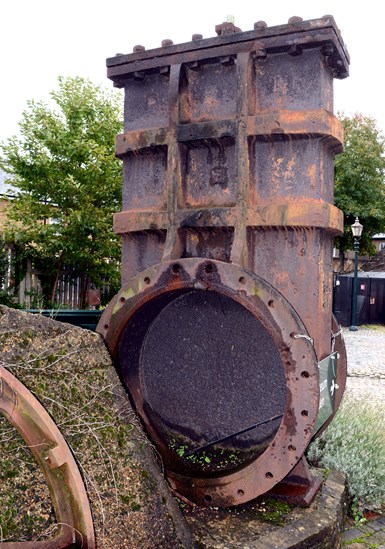
An example of the original wedge-style gate valve designed by James Nasmyth in 1843. This one dates from 1848-1850. Photo credit: Greg Johnson
Gate valves are available in dozens of different materials and several pressure classes. They range in size from fit-in-your-hand NPS ½ inch, through big-as-a-truck NPS 144 inch. Gate valves are constructed of castings, forgings or weld-fabricated assemblies, although casting designs dominate.
One of the most desirable aspects of gate valves is their ability to open fully and leave the flow bore virtually free of encumbrances or friction. An open gate valve offers about the same amount of resistance to flow as a section of pipe of the same port size. As a result, gate valves are still strongly considered for blocking or on/off applications. In some valve nomenclature, a gate valve is called a block valve.
Gate valves are generally bad choices for regulating flow or operating in any orientation other than fully open or fully closed. Using a partially open gate valve for throttling or regulating flow can result in either damage to the disc or body seat rings, due to the seating surfaces banging against one another in the partially open, turbulence-inducing flow environment.
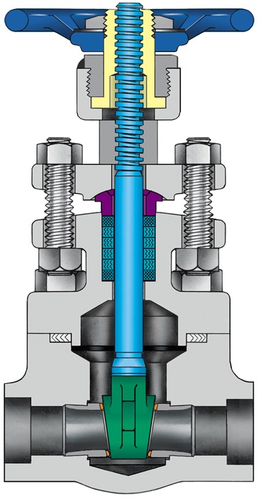
From the outside, most gate valves look somewhat similar. However, inside there are a host of different design possibilities. Most gate valves consist of a body and bonnet that contains a closure element, called a disc or a gate. The closure element is attached to a stem that passes through the bonnet of the valve, ultimately interfacing with a handwheel or other actuation device to operate the stem. Pressure around the stem is contained with a packing material that is compressed into a packing area or chamber.
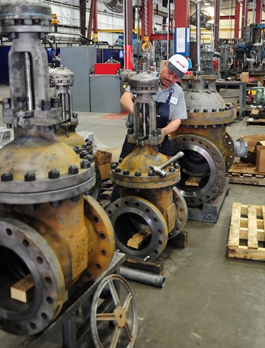
Gate valves generally have a low total cost of ownership. They are relatively easy to manufacture and are easy to repair. Photo credit: Greg Johnson
The motion of a gate valve’s disc upon the stem dictates whether the stem rises during opening or threads into the disc. This reaction also defines the two major stem/disc styles of the gate valve: the rising stem or the non-rising stem (NRS). The rising stem is the overwhelmingly popular style of stem/disc design for the industrial market, while the non-rising style has merited longtime favor with the waterworks and plumbing industry segments. Some marine applications where gate valves are still used and space is tight, also utilize the NRS style.
The most common stem/bonnet design in use on industrial valves is the outside screw and yoke (OS&Y). The OS&Y design is preferred for corrosive environments because the threads are outside the fluid containment area. It also differs from other designs in that the handwheel is attached to a bushing at the top of the valve yoke, and not to the stem itself, thus the handwheel does not rise as the valve is opened.
The word “trim” is often overheard when valve professionals are talking about industrial gate valves. Trim has nothing to do with how slim and fit a valve is; rather, it refers to the internal components of a valve that are exposed to great stress or subject to a harsh combination of erosion and corrosion. In a gate valve, the trim components are the stem, disc seating area, body seats and backseat, if applicable. Common utility bronze or brass valves usually have trim parts of the same material as the body and bonnet. Cast and ductile iron valves have either all iron trim components or occasionally bronze trim. The term for an iron valve with bronze trim is “iron body, bronze mounted” (IBBM).
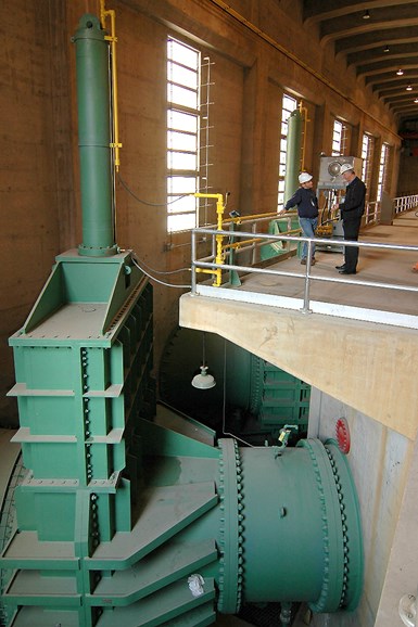
This is one of the eight 90-inch gate valves located in the bowels of Hoover Dam. Photo credit: Greg Johnson
Steel valves can be furnished with a number of different trims. Stellite, Hastelloy, 316ss, 347ss, Monel and Alloy 20 are some of the materials regularly used for gate valve trim.
The heart of the gate valve is the closure element, which can be of two designs, either the wedge or the parallel seat. The wedge design is the most popular and has been around since invented by famous British engineer James Nasmyth in 1843. The wedge style utilizes the slightly angled disc mating with the same angled valve body seats to affect a tight closure. These valves are seated by applying torque to push the disc firmly into the seats. Three types of wedge disc are available:
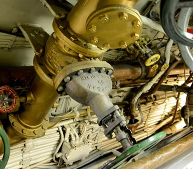
Space is at a premium on ships and NRS gate valves have been used in these applications for decades because they require less room than OS&Y gate valve designs. Photo credit: Greg Johnson
Wedge gates are guided by grooves or ribs cast or welded into the body of the valve. These wedge guides keep the disc in alignment as it opens or closes and also keeps the disc from sliding against the downstream seat during opening and closing.
The other gate valve disc style is the parallel seat design. Parallel seats may be spring loaded to provide for a tighter seal or create positive sealing in the upstream direction. Parallel seated valves are position seated, in that the position of the disc dictates the sealing efficacy, and not the amount of force (torque) applied to the disc by the stem.
Gate valves generally are made of two principal parts: the body and the bonnet. These comprise the pressure-containing envelope of the gate valve. There are a variety of designs for the interface of these two components.
Also in the gate valve family are knife and sluice gates. The bonnetless knife gate is especially suited for use in slurries such as in pulp and paper mills.
This small gate valve is a common design in sizes NPS 1/2-2 inches. The tapered disc is clearly visible. Photo credit: Greg Johnson
Knife gates are very thin, only slightly wider than their closure element (disc). Because of their unique geometry and thin cross-section, knife gates are limited to low pressure applications.
In appearance, the sluice gate doesn’t look like it even belongs in the gate valve family; however, based upon its sliding disc design, it is characterized as a gate valve. Sluice gates are limited to very low pressures — in most cases, simple head pressure. They are used primarily in wastewater and irrigation systems.
While the quarter-turn valve has achieved a large chunk of the gate valve market share over the past 50 years, there are still industries that rely heavily on them, including the oil and gas industry. Crude or liquid pipelines are still the home to parallel seat gate valves, despite the inroads that ball valves have made on the gas pipeline side.
In the larger sizes, the gate valves are still the primary choice for the refining industry for most applications. The robustness of design and total cost of ownership (which includes the economics of repair) are points that make this legacy design desirable.
)
An NPS 36 pipeline-style parallel seat gate valve is unloaded at one of the U.S. Strategic Petroleum Reserve locations. Photo credit: Greg Johnson
Application-wise, many refinery processes utilize temperatures above the safe operating temperature of Teflon, which is the primary seating material in floating ball valves. The high-performance butterfly valve and metal-seated ball valve are beginning to see more use in refinery applications, although their total cost of ownership is often higher than that of the gate valve.
The waterworks industry segment is still dominated by iron gate valves. They are reasonably inexpensive and long-lasting, even in buried applications.
The power industry utilizes alloy gate valves for applications involving very high pressure and very high temperature. Although some newer Y-pattern globe valves, and metal-seated ball valves designed for blocking service are found in power plants, gate valves still find favor for plant designers and operators.
)
A trio of NPS 36, NRS gate valves are seen in manifolds at a water treatment facility. Photo credit: Greg Johnson
Steel and iron are the most popular materials for gate valve construction, with steel being the choice for most industrial applications and iron for water, wastewater and heating, ventilation and air-conditioning (HVAC). Other materials popular for gate valve construction include stainless steel, bronze and high alloys such as Hastelloy and Inconel.
Standards for the design and construction of gate valves are published by the American Petroleum Institute (API), Manufacturers Standardization Society (MSS), American Waterworks Association (AWWA) and American Society of Mechanical Engineers (ASME).
Gate valves are still the primary choice for many service applications. Their cost of manufacture to value ratio is still very high. On typical petrochemical and refining projects today, the percentage of gate valves on the requisition is about 60%.
Mark Twain once said, “The rumors of my death have been greatly exaggerated.” Although the ball, plug and butterfly valve segments have been gaining market share for decades, the venerable gate valve can respond the same way — the rumors of its demise have been exaggerated.
Greg Johnson is president of United Valve. He is a contributing editor to VALVE Magazine and a current Valve Repair Council board member. He also serves as chairman of the VALVE Magazine Advisory Board, is a founding member of the VMA Education and Training Committee and is past president of the Manufacturers Standardization Society. Reach him at greg1950@unitedvalve.com.


