


Published April 7, 2026
Why engineered mounting kits are critical to valve automation integrity.
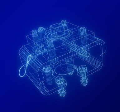
For decades, mounting kits have been treated as commodity hardware – an afterthought – compared to valves, actuators and instrumentation. Yet in practice, the mounting kit is the structural backbone of many automated valve assemblies: the mechanical interface that transfers torque, thrust and external loads between actuator and valve. When improperly engineered, it may become a primary contributor to premature valve failure, misalignment, fugitive emissions and unplanned downtime.
Industry has increasingly recognized this risk.
In response, formal standards were introduced to address the complete valve automation assembly, including its mounting kit. In 2011, the International Organization for Standardization released ISO 12490: Mechanical Integrity and Sizing of Actuators and Mounting Kits for Pipeline Valves. This was followed by the American Petroleum Institute’s API 6DX in 2012.
While originally written for pipeline valves, these requirements are now widely adopted across refining, chemical processing, power generation and general industrial automation.
Since 2023, the Manufacturers Standardization Society (MSS), the International Society of Automation (ISA) and the International Organization for Standardization (ISO) have released mounting kit standards focused specifically on actuator-to-valve mounting components. They expand beyond pipeline applications and establish comprehensive design constraints, dimensional requirements, material expectations and performance criteria for precision, consistency and reliability across automated valve assemblies.
The intent is clear: Mounting kits are not accessories — they are structural components.
The two original standards (ANSI/API 6DX and ISO 12490) required mounting kits to transfer all loads from actuator to valve, including forces equal to or exceeding 1.1 times maximum torque or thrust, taking into account the following:
▪ Pneumatic or hydraulic actuators at maximum operating pressure
▪ Spring-return actuators at maximum spring compression
▪ Electric actuators at stall torque or 100% torque switch setting
The standards specified allowable tensile, shear, torsional and bearing stresses, which were derived from ASME BPVC Section VIII (2004).
Welding was also considered, and fillet welds needed to use a strength efficiency factor of 0.75. The bolting in mounting kits was not permitted to be subjected to shear forces.
The recently released standards built upon this foundation by introducing clearer performance expectations for actuator-to-valve mounting components, including stiffness, alignment integrity and dimensional repeatability. Excessive deflection or misalignment can introduce side loading on valve stems, which can accelerate packing wear, increase operating torques and contribute directly to fugitive emissions. This is where engineered mounting kits differentiate themselves from generic brackets.
It is critical that mounting kits are designed using engineering analysis, controlled tolerancing and application-specific geometry to maintain concentricity and parallelism between the actuator drive, coupling and valve stem — protecting both sealing integrity and mechanical longevity.
Modern engineered mounting kits now draw from a growing ecosystem of international standards, including:
▪ ANSI/API 6DX: Standard for Actuators and Mounting Kits for Valves
▪ ISO 12490: Mechanical Integrity and Sizing of Actuators and Mounting Kits
▪ ISO 5211: Industrial Valves — Part-Turn Actuator Attachments
▪ ISO 5115: Industrial Valves — Part-Turn Valve Actuation
▪ ISO 5640: Industrial Valves — Mounting Kits for Part-Turn Actuator Attachment
▪ MSS SP-101: Part-Turn Valve Actuator Attachment — FA Flange and Driving Component Characteristics
▪ MSS SP-162: Design Requirements for Actuator-to-Valve Mounting Components
▪ ISA 96.09.01: Guidelines for the Specification of Mounting Hardware for Quarter-Turn Valve Actuators
Together, these documents specify the importance for: mechanical integrity, interface geometry, bolted joint design, bracket stiffness and alignment control. Collectively, they reinforce a system-level engineering approach to actuator mounting.
Among all mounting kit components, the intermediate support, or bracket, is often the most underestimated. API 6DX explicitly states: “Deflections of the mounting kit shall not prevent the valve closure member from reaching the fully closed or fully open position or restrict actuator functionality.”
ISO 5115 further adds: “The intermediate support design shall be sufficiently strong by design and material selection to ensure no visibly discernible movement of the actuator from twisting or warping of the intermediate support during operation.” These statements elevate stiffness from a convenience to a performance requirement. If mounting brackets are not designed and manufactured to these guidelines, they can experience:
▪ Side loading on valve stems
▪ Uneven coupling engagement
▪ Increased packing wear
▪ Reduced actuator efficiency, or
▪ Accelerated mechanical fatigue
MSS SP-162 reinforces the proper design of a mounting bracket by formal izing stiffness and dimensional control expectations for mounting components. Brackets are to be engineered for rigidity using material selection, section geometry and proper analysis, ensuring torque is delivered to the valve stem, not absorbed through bracket deformation.
The mounting kit standards require mounting kits to maintain: parallel mounting faces, concentric bolt patterns and alignment between actuator drive, coupling and valve stem. These are not cosmetic tolerances — they directly impact operational life.
Misalignment can result in side loading on the valve stem, degrading seals and can increase the required torque to open and close the valve. Engineered mounting kits control these parameters through proper design, machining and inspection.
Multiple standards now converge on a single philosophy: Bolted joint connections must rely on friction, not bolt shear.
▪ ISO 5115 requires fasteners to be manufactured to a specification with defined minimum mechanical properties. Without knowing the minimum mechanical properties, proper tightening techniques could not be defined.
▪ API 6DX mandates bolt preload calculations sufficient to prevent slippage in assemblies lacking anti-rotation features.
▪ ISA 96.09.01 formalizes this further:
» All bolted connections within an assembly shall be slip-critical joints.
» Slip-critical joints depend on calculated bolt tension to generate clamping forces that exceed applied shear loads — preventing joint movement under maximum actuator torque.
» Without this engineering discipline, bolts become structural members, leading to fatigue, loosening and eventual failure.
Every automated valve assembly is only as reliable as its mounting system. ANSI/API 6DX and ISO 12490 established the foundation for mechanical integrity. MSS SP-162, ISA 96.09.01, ISO 5115, ISO 5640, ISO 5211, and MSS SP-101 extend that framework — bringing stiffness, alignment, fastener performance and system integration into sharper focus. Together, these standards rein force a simple truth: Engineered mounting kits — designed, analyzed, fabricated and inspected as mechanical systems — protect valves, actuators and ultimately plant operations.

About the Author: Tony Lambert is president & co-owner of VanAire, Inc — a Gladstone, Michigan-based manufacturer of engineered valve automation hardware with products on all seven continents, all five oceans and even outer space.
Valve Basics is your gateway into the world of valves and actuators. Split into
two programs, Valve Basics provides an overview of valves, actuators and valve
automation, and how they are used in various applications.
The Valves 101 program covers the major valve types, including linear, check,
quarter-turn and pressure-relief, plus actuation basics. The Valves 201 program
is offered for those who want to take the next step in learning about critical
flow control products, including actuators, controls, automation and more.
For more information visit the VMA website at vma.org.


Enhanced AspenTech Inmation OT Data Fabric aims to accelerate enterprise-scale intelligence.
May 13, 2026
Securely extends visibility of operator graphics across the enterprise.
April 24, 2026
Mouvex, a brand of PSG, a Dover company, and manufacturer of specialty pumps, announced an enhanced version of its G-Flo Series eccentric disc pump, now capable of handling fluids at temperatures as high as 320°F (160°C). This upgrade makes the G-Flo Series a solution for high-temperature chemical applications, including PVC additives, starch, resins, acrylic acids and more.
April 24, 2026
