Understanding Torque-Seated and Position-Seated Valves
When commissioning an isolation valve, you must ask yourself whether it is torque-seated or position-seated.
#basics
Historically, most valves were torque-seated like the ubiquitous gate valve. Position seating was introduced when quarter-turn valves came into common use in the mid-1900s. But over the last 50 years, even some quarter-turn valves are eccentric and torque-seated. Hence, there is no clear directive as to which valve types have which seating arrangements. It is up to the user to evaluate each valve purchase to understand the type of seating arrangement and ensure the valve’s ability to seal.
TORQUE SEATING
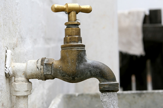
We all grew up with hose bib valves (Figure 1), which should have taught us two important valve principles. First, “Righty-Tighty” and, second, the “Tighter the Valve, the Better It Seals.” For the hose bib, turning the handle in a right-hand rotation or clockwise direction increases the force between the valve disc and the rubber sealing washer making the valve seal tighter. The hose bib is an example of a torque-seated valve.
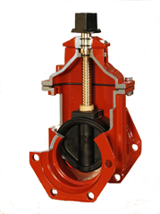
Similarly, the resilient-seated gate valve is torque-seated. It is commonly found below ground in water mains and adjacent to fire hydrants. As shown in Figure 2, the gate travels up and down in the valve body as the stem is rotated. The seal is made by compressing the rubber-coated gate against the body interior. Manufacturers typically specify an operating torque for properly seating the valve at the rated working pressure, which will vary by size. The torque may be as low as 30 ft-lb for a 4-inch gate valve and as high as 150 ft-lb for a 12-inch valve. It is best to consult the operation and maintenance guide for the actual valve model. Excessive torque (i.e., greater than 300 ft-lb) can damage any valve.
POSITION SEATING
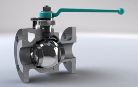
Contrast the hose bib and gate valve with a quarter-turn ball valve commonly found in a basement for the water supply shutoff (Figure 3). The quarter-turn ball valve works on a different principle. In this valve, a spherical ball presses against a soft seat. When the valve is closed, the greater the pressure in the line, the greater the force between the ball and the seat. The rotation of the handwheel or handle positions the ball in the closed position, but does not create any additional force between the ball and the seat. The geometry of the seating arrangement is concentric. Applying excessive force on the handwheel will simply break off the closed-position tab on the handle. The ball valve is an example of a position-seated valve.
SAME VALVE TYPE, BUT VARYING SEATING ARRANGEMENTS
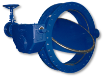
Unfortunately, the type of seating arrangement can vary for the same type of valve. For example, an on-center or single-offset butterfly valve built in accordance with AWWA C504 (Figure 4) works similar to the ball valve and is position-seated. The disc in these valves can be rotated completely through the seat and the best sealing is achieved when the disc is positioned in the exact closed position. Over-rotating the valve will simply cause the valve disc to pass through the seat and leak. The closed position is controlled by mechanical stops in the gear actuator. Over-torqueing the handwheel or operating nut will only damage the gear and not make the valve close any tighter. Hence, if leakage is detected, the valve should be cracked open a few times to flush any foreign debris from the valve. If leakage persists, then the closed stop setting in the actuator or the valve seat may require adjustment. Over-turning the handwheel will not make it seal any better.
However, all butterfly valves are not the same. For double-offset and triple-offset butterfly valves, excess rotation of the valve will cause greater interference between the disc and the seat because they are eccentric. These types of butterfly valves are torque-seated and with the proper torque, they will seal drop-tight in both flow directions.
A TORQUE-SEATED VALVE CAN ALSO BE POSITION SEATED
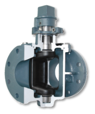
Similarly, quarter-turn eccentric plug valves (Figure 5) are built in accordance with AWWA C517 and are eccentric and seal tighter as the valve is further closed. Plug valves are typically used in sewage or grit-laden applications where the eccentric action prevents seat wear. Ironically, though, eccentric plug valves are adjusted in the factory as position-seated valves. If a higher pressure rating is needed or the plug becomes worn, the closed stop position in the actuator can be used to position the plug farther into the seat to seal tight. The eccentric plug valve has all of the features of a torque-seated valve, but is commissioned as a position-seated valve.
IMPORTANCE OF VALVE ROTATION
Before leaving plug valves, we should mention that the “Righty-Tighty” rule is not universal. While right-hand operation is the general rule, some municipalities in the U.S. require opposite rotation. Valve manufacturers in the waterworks industry designate these special valves as “Open Right” and commonly paint the operating nuts red. In addition to knowing that a plug valve is position-seated, you should also make note of its direction of rotation. To assist the user, all handwheels and nuts should have an arrow indicating the direction of opening.
POWER ACTUATION
It goes without saying that once you know the rotation of your valve and its seating arrangement, any power actuator will need to be set up the same way. Motor actuators can be set to close the valve based on torque switches or limit switches. A position-seated valve (e.g., ball valve) will utilize the limit switches to properly seat the valve at the exact seating position. For position-seated valves the torque switch can still be used, but as over-torque protection in case there is an obstruction in the line. A torque-seated valve (e.g., gate valve) will use the torque switches to properly seat the valve at the required torque setting. There is often a torque switch electrical bypass in the opening direction so that more torque is available to break the valve out of its seat.
By understanding the two types of seating arrangements, torque-seated and position-seated, valve users can better maintain and maximize the effectiveness of their valves.
REFERENCE: American Water Works Association (AWWA), M49 Quarter-Turn Valves: Headloss, Torque, and Cavitation Analysis. 3rd Ed. 2017.
John V. Ballun is President and CEO of Val-Matic Valve and Manufacturing Corp. (www.valmatic.com) in Elmhurst IL. He is a member of the VMA Communications Committee and a VMA Board Member. Reach him at jvb@valmatic.com.
RELATED CONTENT
-
Ancient Roman Valves
The story of water supply in the ancient Roman Empire is grand.
-
Fundamental Operation of Pilot-Operated Safety Relief Valves
In this second of a series, we explore another type of pressure relief valves used in common applications.
-
Introduction to Pressure Relief Devices - Part 1
When the pressure inside equipment such as boilers or pressure vessels increases beyond a specified value, the excess pressure may result in a catastrophic failure.




 Unloading large gate valve.jpg;maxWidth=214)

