A Primer on Castings
Valve components, such as bodies, bonnets and caps, are manufactured either by forging or casting.
#components #standards #basics
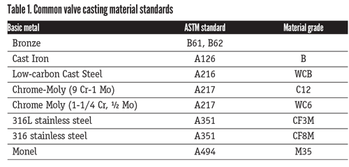
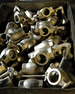
Virtually every metal can be cast into valve components. From small bronze valves that populate the big box store plumbing shelves to the largest iron valves found in waterworks projects, all are created from castings. Some materials, such as bronze and iron, are easier to cast than others. Iron founding is a particularly forgiving process and its use in large valve castings is legendary. Today’s foundries regularly produce iron butterfly valve castings up to NPS 144 and gate valve castings up to NPS 108.
Two primary casting processes are in use today for valve components. The oldest is sand casting, where molten metal is poured into a mold of sand held together with binding compounds. The second process is called the investment or lost-wax process. Although it has been used for corrosion-resistant valve components for about 50 years, the past 25 of those years have seen use expanded tremendously for low-carbon steel valve castings. The lost-wax process is especially popular with Asian foundries and is the defacto method for casting small- to moderate-size valve components.
HOW THEY WORK
The sand casting process begins with a wood or metal pattern. This pattern is placed in a box; then specially prepared sand is packed rigidly around the pattern. When it’s removed, it leaves a cavity corresponding to the shape of the pattern. The mold is baked to strengthen the sand/binder surface, creating the outer surface of the part to be cast. When inner ports or voids are required, such as in valve castings, a sand core is prepared and placed inside the mold box. The usual mold box is comprised of two parts—the cope (top) and drag (bottom). If needed, tiny spacers called chaplets are used to keep the core from falling out of alignment and touching the mold wall. Molten metal is then poured into the mold and allowed to cool.
In the lost-wax or investment process, a wax pattern is created in a wood or metal mold. This pattern is then covered with several layers of refractory slurry. When the slurry is the proper thickness, the wax is melted out, leaving a smooth outside casting diameter pattern. As with the sand casting process, cores are installed in these patterns. Molten metal is then poured into the casting and allowed to cool.
The casting process is very straightforward; however, several factors present challenges for creating an acceptable casting free of detrimental defects. The metal must be poured at the right temperature to allow for proper solidification in the mold. The molten metal must not be poured too fast or with too much velocity because gas bubbles or pattern damage may occur. Because of the many variables in the casting process, a foundry must have experience in each different alloy it pours.
One tool at the disposal of the foundries that helps to ensure a quality casting is a virtual casting process using casting simulation software to predict the soundness of the casting during the pour and after cool-down. This software is very much like finite element analysis because it graphically creates a thermal diagram of the proposed pour. To achieve accurate results, all the parameters and variables have to be properly assessed and entered into the program. The use of casting simulation software can help the foundry develop or improve pouring practices, which if followed closely, will yield increasingly better castings.
STANDARDS AND QUALITY CONTROL
Casting quality begins with an accurate pattern and correct rigging (patterns, molds, cores and boxes). After the mold is prepared and filled with molten metal, quality processes are put into motion. The first is to create a test coupon, which is a sample of the metal cast during a pour. The mold of each casting and test coupon to be poured during the heat is embossed with a specific heat number. This heat number will allow traceability between the test coupon and the castings poured during a specific heat.
After the pour is made, the test coupon is subjected to a variety of chemical and mechanical tests. The results of these tests determine the initial acceptability of castings in the pour. Because of the differences between the geometry and size of the test coupon and the actual casting, slight variations will occur in the test results. The test coupon is also subjected to any subsequent heat treatments performed on the castings in the heat.
Quality assessment of the actual castings is performed a number of ways. The most widely used volumetric (evaluation of the interior of the casting) inspection method is radiography. Radiography results can assess the overall workmanship of the foundry or can detect potentially catastrophic defects in the metal. Additional non-destructive examinations (NDE) performed on valve castings include dye penetrant examination, which detects surface irregularities, and magnetic particle examination, which can detect surface and slightly subsurface irregularities.
Two new casting specifications have been written over the past 24 months that will aid foundries, valve manufacturers and end users. The first is API 20A, Carbon Steel, Alloy Steel, Stainless Steel and Nickel Base Alloy Castings for Use in the Petroleum and Natural Gas Industry. The second is MSS SP-147, Quality Standard for Steel Castings Used in Standard Class Steel Valves, Sampling Method for Evaluating Casting Quality. The availability of these standards should aid in the quest for continuous casting improvement.
Foundries worldwide have made large investments in the latest melting and NDE equipment to assure the continuing quality of their products. Items such as vacuum-degasing furnaces and linear accelerators are becoming staples in 21st century foundries. Castings are still an excellent economical choice for valve components, and it appears they will be for years to come. VM
This is part one of a two-part article. Part two, which will cover forgings in addition to castings, will appear in the Winter 2015 VALVE Magazine.
GREG JOHNSON is president of United Valve (www.unitedvalve.com) in Houston. He is a contributing editor to VALVE Magazine, a past chairman of the Valve Repair Council and a current VRC board member. He also serves as chairman of VMA’s Education & Training Committee, is vice chairman of VMA’s Communications Committee and is president of the Manufacturers Standardization Society. Reach him at greg1950@unitedvalve.com.
RELATED CONTENT
-
Updated Piping Codes and Valve Standards
As with every intended use for valves, piping carries its own set of standards that valve companies and users need to understand.
-
New Requirements for Actuator Sizing
After decades of confusion, the American Water Works Association has created new standards for actuator sizing that clear up some of the confusion and also provide guidance on where safety factors need to be applied.
-
Creating a Standard for Severe Service Valves
Severe service valves are offered in several standard designs, including non-return, isolation and control types.


 Unloading large gate valve.jpg;maxWidth=214)