
Produced by


Published October 30, 2023
The compact design, simplicity of use, ease of repair and wide performance capability have helped to make the ball valve a dominant design in modern industrial applications.
By Updated by Greg Johnson, Editorial Advisory Board Member
The invention of the ball valve has proven to be a revolutionary development for the valve industry, supplying numerous unique solutions that meet modern flow control requirements. But its successful application was not immediately evident.
Early in the life of the ball valve, its current assets and values were not realized. The lack of machining technology to make a truly round ball did not exist. And sealing materials of the time, associated with the use of natural rubbers, were very limited and prevented the ball valve from being applied to any significant industrial use.
During World War II and into the 1950s, machining technology developed for the war effort allowed the inherent advantages of the ball valve to be introduced into military usage. The development of synthetic materials such as polytetrafluoroethylene (PTFE), often known by the brand name Teflon, paved the way for industrial sector applications.
Today, the ball valve is used in a wide array of applications for flow control of liquids, gases and even solids. These applications are in temperatures that range from -450°F (-267°C) to more than 1600°F (871°C). Pressures can range from full vacuum to in excess of 20,000 psi.
The major components of the ball valve are the body, ball, seats and stem. These components can be made from a wide variety of materials. Ball valves are offered in numerous end connections, including flanged, threaded, weld end and wafer, as well as specialized end connections.
Ball valve designs fall into the quarter-turn category of valves, including plug and butterfly valves. This quarter-turn category means the valve stem is turned 90 degrees for operation.
The most common of these designs are the floating design and the trunnion-mounted design. They are typically bi-directional in sealing and can be oriented in any position or direction for opening and closing.
Some of the basic advantages these ball valves have over other designs include:
The floating ball design (Figure 1) initially compresses the ball between soft seats when the valve is assembled. This forces the seat material to cold-flow into the pores of the ball, creating a vacuum and low-pressure seal. In the closed position, line pressure forces the ball into the downstream seat. This provides for a tight shutoff over the pressure and temperature design of the seat.
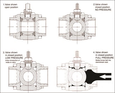
Figure 1: How floating ball valves work.
The floating design is most common in a size range from 1/4 to 12 inches, though some manufacturers offer sizes up to 18 inches. Floating ball valve size is limited by the size and weight of the ball, and by the torque required to rotate it as the size increases.
Trunnion-mounted designs (Figure 2) work just the opposite of the floating design. In the trunnion design, the ball cannot float but is rigidly located by the stem on top and a shaft or trunnion, utilizing bearings on the bottom. The seats are compressed against the ball using a spring or springs to develop the initial low-pressure seal.
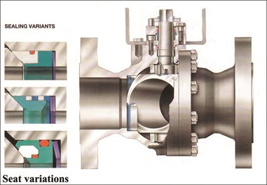
Figure 2: Trunnion design.
Trunnion valve seats are designed with seals to be process-energized, with increasing pressure forcing the upstream seat harder into the ball. This provides for a tight shutoff over the pressure and temperature design of the seat.
Trunnion designs typically take over where floating ball design application leaves off and can be found in a size range from 3-72 inches. The advantage of this valve design becomes apparent as the valve size grows.
The weight of the ball and the operating torque are not factors, as the seats in a trunnion valve do not support the ball. This means the trunnion valve seats can specialize in sealing the ball, allowing much larger valves with smaller actuation than can be made in any type of floating design.
The ball valve body can be cast, forged or machined from about every conceivable metal. This is due to the ball valve’s simple and compact design. Applicable metals include:
Ball valves are also made in a variety of plastics and polymers, including PVC, polyethylene and polypropylene. Ball valves also can be lined with polymers and plastics, and can be made from or lined with ceramics such as alumina and zirconia.
The basic design of valve bodies in the United States meets the ASME (American Society of Mechanical Engineers) standard B16.34 guidelines. These standards determine wall thicknesses, stress levels and other parameters in conjunction with pressure-temperature relationships for most ferrous alloys.
B16.10 guidelines also specify the acceptable dimensions of many classes of valves, such as industry-specific standards like the API (American Petroleum Institute) standard 6D for pipeline valves and API 608, “Metal Ball Valves—Flanged, Threaded, and Welding Ends.” These specifications control the dimensions, materials and applications to ensure the valve design remains consistent from manufacturer to manufacturer and is safe for the intended application.
Ball valves in waterworks service are covered in AWWA (American Waterworks Association) standard, C507-18, “Ball Valves, 6 in. Through 60 in. (150mm through 1500 mm).”
Many other countries have national standards, and several organizations foster international standards as well. Valve manufacturers wishing to enter the global market must conform to ISO (International Organization for Standardization), PED (European Commission — Pressure Equipment Directive), CE (PED) and ATEX (Bureau Veritas) standards, among the many others that exist, such as in China and Russia. Meeting these standards has become a mandate for trade with the European Union, as well as JIS standards for Japan and similar requirements elsewhere.
Other common specifications for the rating of ball valves include WOG (water/oil/gas), CWP (cold working pressure) and WSP (working steam pressure). These ratings are more limited and are typically established by the individual manufacturer. All of these specifications will establish a pressure/temperature curve for the valve design, which lowers the pressure rating as the temperature rises.
Body designs are divided into four basic configurations:

Figure 3: Three-piece ball valve design.
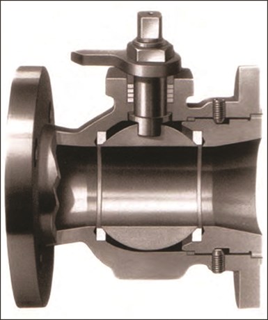
Figure 4: End-entry design.
Figure 5: Split-body design.
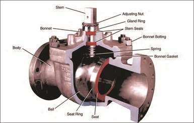
Figure 6: Top-entry design.
The flow control element of the ball valve is, of course, the ball. The ball acts against the seat and can stop or control flow through the valve. Balls are designed and manufactured to exacting tolerances for surface finish and spherosity, or roundness. Both the ball and seat are critical to smooth operation, reduced torque and good sealing performance, especially when metal seats and metal-to-metal sealing are required. The ball port configuration can vary from a standard straight and through-hole style to a multi-port style for ball valves that offer three- to five-way port designs (Figure 7). While most ball valve designs use a full spherical ball, there are also designs that use a half ball (sector) and those that use cam action to force the ball into the seat.
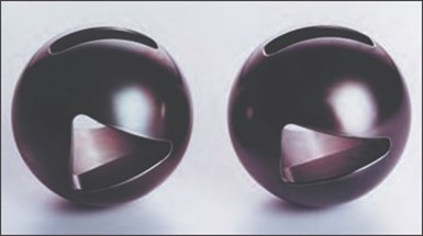
Figure 7: Configured port balls.
The balls used in valves are machined from many materials, including metal, ceramic or plastic. Metal balls can be enhanced with a variety of coatings or surface treatments. These are used to provide improved wear resistance, corrosion resistance or high hardness to prevent galling, which is where the base metal does not hold up.
Surface enhancements can include polymers, flame spray, electroless nickel, PVD coatings and diffusion processes such as nitride and boride application. These enhancements are a major reason for the successful application of ball valves in the wide variety of applications in which they are currently used.
The enhancement of seat design and technology has allowed the ball valve to expand into a wide array of applications. These seats can provide multiple functions, depending on the valve design and the seat material.
They need to provide tight shutoff in the case of resilient materials, as well as support the ball in floating ball designs, resist the service and provide good cycle life. Seats can also incorporate characterized ports for flow control purposes.
Soft seat designs are commonly referred to as “jam” designs that provide full-face contact when assembled, or as flexible lip designs that have reduced face contact for lower torque and improved cycle life.
Different body designs will use these or variations of the basic soft seat design. Many manufacturers’ designs also provide some form of cavity pressure relief, preventing seat and valve damage in the event of trapped cavity pressure from the media trapped in a closed valve.
Soft seat materials used today include, but are not limited to:
Metal seat designs are used in ball valves to handle the most severe applications, including high pressure, high temperature, abrasiveness and flow control.
There are many metal seat designs in use, the most common of which incorporate seats of solid metal, surface hardened or coated, and lapped to a ball that has been similarly hardened. This matches the ball and seat surfaces to affect a good seal.
Other designs include sintered metal impregnated with graphite or PTFE, and even some flexible designs. Resilient seats are required to be bubble-tight, yet most valves with metal seats are allowed some leakage per leakage specification rates of metal-seated ball valves. The most common of these specifications are MSS-SP-61 and API 598. Other specifications that are commonly applied to metal-seated ball valves include FCI 70.2 and API standards.
Most metal-seated, floating ball designs use springs and/or seals to compress the seats against the ball, and to seal the backside of the seat for low pressures. The ball floats against the downstream seat as pressure increases, providing shutoff over the pressure and temperature design of the seat, similar to the action of the soft-seated version.
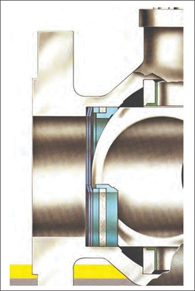
Figure 8: Trunnion metal seated ball valve.
In trunnion designs (Figure 8), springs and often several seals are used to capture the line pressure, forcing the seats harder against the ball as the pressure increases. Some manufacturers even machine the seating surface into the valve body, eliminating springs and seals in one direction. This, however, typically results in a unidirectional valve operation.
The stem is used in the ball valve to rotate the ball to an open or closed position, or to an intermediate position for flow control. Materials considered for stems have to withstand more than just the pressure of the body, ball or seats. They have to resist the corrosion and temperature of the process while retaining enough strength to withstand the torque applied to them when the valve is operated. For this reason, higher strength and corrosion-resistant materials are usually selected for stem manufacturing.
As the stem is the connection to the ball, it must pass through the body so it can be operated externally. This requires that the stem have seals in order to prevent the media in the valve from escaping. The seals must seal bubble-tight, withstand the fluid corrosion and temperature, and provide good cycle life.
Typical stem seal materials include polymers such as PTFE and PEEK. For higher temperatures or fire safety, graphite stem seals are typically used. These materials remain flexible over wide temperature ranges and are chemically resistant. In fire-sealed valves, the seals must survive a fire without leaking.
Rotary quarter-turn valve designs like the ball valve have the best-performing stem seals. This is due to the stem moving in a rotary motion as opposed to a rising stem motion found in gate and globe valves. With today’s environmental concerns and regulations, stem seal performance is critical to valve manufacturers and end-users.
Stem seal designs fall into two basic categories: stem-energized seals and body-energized seals (Figures 9 and 10). These designs use many different types of seals, with the most common being flat ring, chevron, cup and cone and monolithic elements.
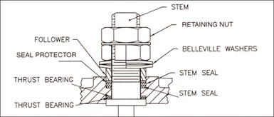
Figure 9: Stem-energized stem seal.
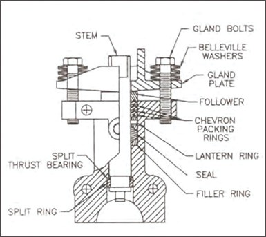
Figure 10: Body-energized stem seal.
Stem Energized. In this design, there are usually multiple seal rings. Some of these are inside the valve body pressure boundary that becomes the primary seal, and others are outside the pressure boundary in what is called the “packing” or “stuffing” box.
These seals are compressed or energized through the action of pulling up on the stem with a stem nut, which simultaneously compresses the upper seals with a packing follower. Most of these designs incorporate Belleville springs to live load the seals. This makes the stem seal assembly self-adjusting and temperature compensating, allowing for longer cycle life before readjustment is needed.
Body Energized. In this design, sealing is accomplished above the pressure boundary in the stuffing box, again using single or multiple seal rings. Some manufacturers may use a thrust bearing on the stem below the pressure boundary, but no sealing is actually performed there.
These seals are loaded using a “yoke” or “gland plate,” compressing the seals in the stuffing box using bolts threaded into the body. The design typically utilizes multiple Belleville springs on the bolts to again “live load” the gland plate, making the stem seal self-adjusting.
The advantage of this design is that the stem is free to float within the seals, reducing torque and increasing stem seal life. This design also allows the incorporation of “fugitive emission” designs, which utilize multiple sets of seals, creating additional or redundant seals for toxic and high-cycle applications (Figure 11).
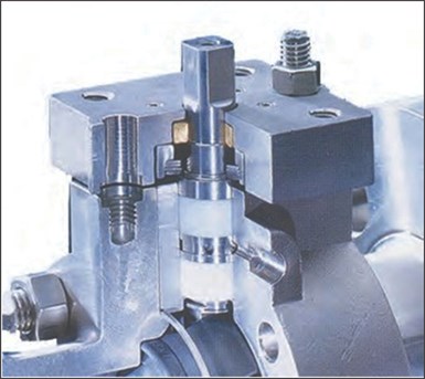
Figure 11: Dual fugitive emissions valve stem.
With the advanced designs and materials offered in modern ball valves, they are utilized in many services and industries. Success in these applications depends on the correct specification of all of these designs and components as discussed.
Ball designs are not limited to on/off service. They can be used to divert, control or mix flows. Different functions can be accomplished by having multiple ports for diverting and mixing, or by having a characterized port, such as a V-port, for flow control.
Quarter-turn control ball valve usage is becoming more common in moderate-pressure drop flow control applications. This is due to the process advantages of lower cost, tight shutoff and high accuracy when coupled with digital controls on electric and pneumatic actuation.
There are also specialty ball valve designs for unique applications. These can include valves for cryogenic service, which must handle extremely low temperatures, and valves for high-pressure steam, which must handle extremely high temperatures and pressures.
Other ball valve applications include their use in industries such as pharmaceutical, aerospace, nuclear, biotech and pulp and paper. Applications where they are used include acids and chemicals, slurries, thermal fluids, steam and cryogenics.
Conclusion
The compact design, simplicity of use, ease of repair and wide performance capability have helped to make the ball valve a dominant design in modern industrial applications. And ball valves continue to evolve in order to meet new and more difficult demands.
The industrial sector is placing greater and greater emphasis on safety, the environment, improved efficiency and cost reduction. Thus, the assets of the ball valve will continue to make it an important player with many future roles.
This article was originally written by Brian Hood (Flowserve). It was previously published but has been updated by Greg Johnson, president of United Valve, and member of this magazine’s editorial advisory board.
All images are copyright of Flowserve Corporation.


June 26, 2026
June 5, 2026
Why engineered mounting kits are critical to valve automation integrity.
April 7, 2026
