


Which Gate Valve is Best for Today's Waterworks Systems?
A historical perspective may provide the answer.
#water-wastewater #gate-globe-check
Share
The gate valve is the most common valve used in a waterworks utility system. Gray cast iron metal-seated gate valves have been produced since the 1800s. They are governed by the ANSI/AWWA C500 standard tilted Metal-Seated Gate Valves for Water Supply Service. The standard was developed in 1913 but did not receive the C500 designation until 1953. In 1980, as rubber molding and coating technologies advanced, the waterworks industry introduced the ANSI/AWWA C509 Resilient-Seated Gate Valves for Water Supply Service standard.
The C509 standard, unlike C500, has no allowance for leakage. It also requires more corrosion-resistant coatings. Responding to trends that saw the industry’s migration from cast iron to ductile iron pipe and fittings, field trials were conducted on a reduced wall, ductile iron gate valve beginning in 1985. This advancement resulted in a new standard for resilient-seated gate valves being published in 1999. The standard was designated ANSI/AWWA C515 Reduced Wall, Resilient-Seated Gate Valves for Water Supply Service. The standard leveraged the strength and durability of ductile iron by reducing the wall thickness of the valve. Today, most utilities specify C515 gate valves. Occasionally, however, specifications are published requiring C500 or C509 compliance even when the utility is using C515-compliant valves. These outdated specifications, or erroneous references to older standards, result in confusion regarding which gate valves should be used. More problematic are specifications that require contradictory criteria from multiple standards, which can require a valve that may not exist. These problematic situations result in unintended interpretations of the requirements. To understand the source of the confusion, one must first look at how the standards have evolved and why.
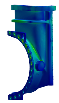
Figure 1: Finite element analysis (FEA).
Photo Credit: American Flow Control
The minimum wall thicknesses required in the C500 standard were largely based on industry experience, valve application and the standard gray iron casting methods used at the time. These limitations resulted in the published wall thicknesses being somewhat arbitrary. Also common to these valves is an allowable leakage that worsens with time, as well as higher operating torques that result from significant friction across the metal seats. The resilient-seated gate valve addresses these primary issues with a one-piece rubber-encapsulated wedge that is leak-tight and that allows for lower operating torques. Originating in Europe, the resilient-seated design was received with widespread acceptance and in 1980 resulted in the development of the C509 standard. The wall thicknesses published in the standard were carried over from the C500 standard, making the C509 wall thicknesses arbitrary as well.
After the introduction of the resilient-seated gate valve, the industry migration from gray cast iron to ductile cast iron continued in the development of the C515 standard. A comparison of these standards reveals only a few differences; they are virtually identical. Unlike C509, the newer C515 standard requires the use of ductile iron for the body and bonnet components. Because of the increased strength and elasticity of ductile iron, the allowable minimum wall thickness requirements are reduced, and the pressure rating has been increased. Different from the arbitrary wall thicknesses in C500 and C509, the wall thicknesses published in C515 were developed using finite element analysis (FEA), along with applied validation testing. Since being published, there has been a significant shift in demand toward ductile iron waterworks valves produced to the C515 standard. Another significant difference in the standard is an allowable 12.5% reduction in wall thickness accounting for casting deficiencies called out in the C500 and C509 standards. This reduction is not allowed in C515. A comparison of the allowable C500, C509 and C515 wall thicknesses appears in Table 1 and shows the differences to be very minimal. Table 1 thicknesses account for allowable tolerances.
After the ANSI/AWWA C515 standard was published in 1999, there were occasional questions about the potential effects of corrosion related to reduced wall thickness. Of particular concern was how material loss, if any, might impact the strength of a valve while under pressure. Companies must address this during the validation of reduced wall designs with coatings. Of note, both C509 and C515 valve castings are typically coated with a fusion-bonded epoxy coating prior to assembly. This coating insulates the individual valve components and protects them against corrosion. Metal-seated C500 valves, upon which C509 wall thicknesses were based, were not coated in epoxy.
|
Minimum Wall Thickness |
|||
|
Size |
AWWA (inches) |
AWWA (inches) |
AWWA (inches) |
|
0.35 |
0.31 |
||
|
0.38 |
0.32 |
||
|
0.44 |
0.34 |
||
|
10 |
0.55 |
0.36 |
|
|
12 |
0.60 |
0.38 |
|
|
14 |
0.66 |
0.45 |
|
|
16 |
0.74 |
0.50 |
|
|
18 |
0.82 |
0.56 |
|
|
20 |
0.85 |
0.56 |
|
|
24 |
0.95 |
0.62 |
|
|
30 |
1.22 |
1.06 |
|
|
36 |
1.35 |
1.31 |
|
|
42 |
1.38 |
1.42 |
|
|
48 |
1.51 |
1.44 |
|
|
54 |
1.93 |
1.44 |
|
|
60 |
2.14 |
1.68 |
|
|
66 |
2.35 |
1.88 |
|
|
72 |
2.56 |
1.94 |
|
Experiments were conducted on the gray iron C509 valve and on a ductile iron C515 valve to determine what effect the reduced wall might have. To simulate advanced corrosion, several ½-inch diameter spots were drilled ¼-inch deep into known high-stress concentration areas, as determined using FEA. Gray iron and ductile iron are known to exhibit similar corrosion properties. The drilled spots simulated worst-case scenarios of compromised wall thicknesses. Both valve models were pressurized until failure. The test was then repeated, and the results were tabulated in Table 2. Performance equal to, or better than, the C509 gray was considered validation of the C515 design.
Even with the castings heavily compromised to simulate corrosion, both valves failed well above their rated pressure. The C509 bonnet failed at approximately 850 psig by cracking along a row of drilled locations near the flange. The ductile iron C515 valve did not fracture despite the wall thickness being less than half of the C509 valve.
|
12-inch Gray Iron Valve |
12-inch Ductile Iron Valve |
|
|
Rated working pressure |
200 psig |
250 psig |
|
Undrilled casting wall thickness (avg.) |
0.70-inches |
0.44-inches |
|
Drilled casting wall thickness (avg.) |
0.45-inches |
0.19-inches |
|
Pressure at failure |
850 psig |
1,200 psig |
|
Method of failure |
Fracture along drilled spots |
Blown bonnet gasket |
Due to a temporary yielding of the bonnet, the gasket lost pressure at approximately 1,200 psig. This flexing is due to ductile iron’s ability to yield. During the test, the C515 castings experienced no permanent deformation. The results of the test validate the wall thicknesses published in the C515 standard and demonstrate performance superior to that of the older gray iron design.

Figure 2: Simulated corrosion of the valve castings.
A test comparing the beam load strength of the valves was also conducted. Unrelated to corrosion, beam loads can develop from settling structures and soil, or pipe misalignment. In the test, a vertical load was applied to the top of a valve assembled between two ductile iron pipes and placed under pressure. The lower flange of the gray iron C509 valve failed at 78,000 lbs. with a vertical displacement of less than an inch. The ductile iron C515 valve did not fail, despite 135,000 lbs. of vertical load and approximately 2 inches of displacement. Instead, the piping system failed at the threaded flange location.
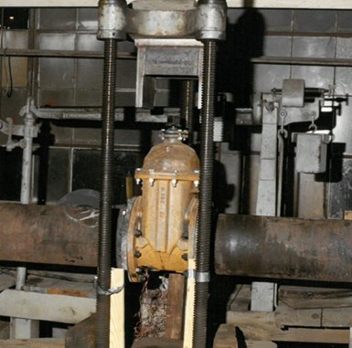
Figure 3: Beam load tests.
The evolution of these standards and the results of these simple but important validations dispel any notion that thicker is always better. Specifications are a critical component to the design of any project. Whatever valve is desired, it is important the specifier be aware of the latest technologies available and stay up to date on product development. The name behind the product is also an important consideration in valve selection. Following these practices will always be in the best interest of the engineer, owner and end user.

Derek B. Scott is the marketing and technical manager for American Flow Control. He holds a B.S. in mechanical engineering from the University of New Orleans and has nearly 40 years of experience in the water and wastewater industries. He is currently responsible for the division’s product engineering and marketing functions. He has served on various stakeholder groups and represents the company on several standards committees, including AWWA, MSS, ASCE, NSF and AWWA, and is chair of the ANSI/AWWA C515 Committee on Reduced-Wall, Resilient-Seated Gate Valves for Water Supply Service.

John R. Helf, PE, is the product engineer for American Flow Control. He holds a B.S. in mechanical engineering from Mississippi State University and is a licensed professional engineer in Alabama. Prior to working with American Flow Control, he was a project manager for American SpiralWeld Pipe, a leading producer of large-diameter municipal water and wastewater transmission piping. He is actively involved in AWWA and MSS standards committees and is a published author.
RELATED CONTENT
-
Ancient Roman Valves
The story of water supply in the ancient Roman Empire is grand.
-
Knifegate Valve Maintenance and Repair
Knife gate valves are used to provide isolation in various applications including oil sands slurries, pulp stock, waste water and power generation.
-
Water Hammer
Water hammer is a shock wave transmitted through fluid contained in a piping system.


 Unloading large gate valve.jpg;maxWidth=214)