Since the early days of water and wastewater treatment plants in the United States, municipalities and industries have continued to expand and upgrade existing plants and distribution infrastructure as well as build new facilities.
But as the existing plants age, sluice gates in service for many decades that haven’t needed replacement may have actuators and controls that have become obsolete more rapidly since this equipment is more complex and susceptible to technology advances.
Automation equipment and processes of 30 or 40 years ago, particularly for fluid power systems, are vulnerable for many reasons. Repairs become difficult because of the scarcity of replacement components, which might be obsolete or out of production. Also, as these systems age, they need more and more service and maintenance. At the same time, suppliers of the automation package could have ceased trading or moved production overseas.
Hydraulic actuators and controls have advanced significantly in recent times, with the integration of digital controls and improved diagnostics. However, there are some municipalities that have had maintenance problems in the past and are looking for a different solution.
Also, even the remotest possibility of a hydraulic fluid leak often precludes the consideration of these types of actuators.
One popular solution is to completely replace the old fluid power system and its central hydraulic power unit (HPU) with individual electric actuators directly mounted on sluice gates. This presents some technical challenges, but the benefits are significant (Figure 1).
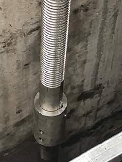
Fluid-power-operated sluice gates usually employ a linear pneumatic or hydraulic cylinder with the piston rod as part of the gate stem to raise and lower the gate. The thrust generated by the cylinder can be replicated by substituting a multi-turn electric actuator with a new, acme-threaded segment of the gate stem (Figure 2).
One of the technical challenges of this actuator modification arises from the torque imparted onto the stem from the action of the rotating actuator output. This introduces a new force that must be constrained. But the problem can be overcome in a few ways.
HOW IT’S DONE
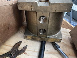
An alternative method is to machine a groove in the stem that fits into a special supplemental base on the actuator with a matching key. This prevents rotation of the valve stem and contains the actuator torque close to the actuator. Although this is more costly, it does prevent stem wind-up and obviates the need to replace the thrust collar at the base of the stem.
A central HPU often uses accumulators in conjunction with electrically powered hydraulic pumps. These allow pressure to be maintained on the system without the pumps running constantly. If there is enough capacity designed into the accumulator bank then it would have the added benefit of being able to store enough pressurized fluid to open or close the gate should electric power be lost.
This emergency operation is not so easy to do with a conventional 3-phase electric actuator. However, some mitigating points exist. Every electric actuator has an easy-to-use manual override provided as a standard feature. On sluice gates, the travel may be significant, so municipalities often have portable power tools to facilitate easier operation on large-travel gates. Additionally, many plants have their own back-up power generators for critical equipment in case grid power is lost.
Removing a central HPU often frees up space for other equipment or controls. The individual electric actuators are themselves quite compact and usually fit into the footprint of the fluid power cylinder that’s being replaced. The old gate control panels often were located adjacent to the HPU in a dedicated building. When operating the gates, a direct line of sight might not have been possible, so visual confirmation of gate position could be difficult.
BENEFITS/CHALLENGES
Electric actuators are self-contained and have their own integrated motor starters and control circuitry. In addition, they have the advantage of their own local pushbutton controls and illuminated position indicators. Because of torque and position sensors integral to the actuator, having an instantaneous readout of torque and travel on a local display is possible. This data also can be stored in the actuator to provide diagnostic information on the gate operation. Although full-travel position sensing can be achieved on fluid power cylinders with an internal encoder, it is difficult to retrofit to existing cylinders.
High-pressure HPU systems require specialized personnel for routine maintenance and accumulator pressure checks. HPUs may be at a remote site where service support is difficult, particularly during off-hours. By contrast, modern electric actuators are environmentally sealed to ensure the internal electric and electronic controls are clean and dry so the maintenance requirements are very low.
The physical change-out of old to new actuators requires access to the gate stem. This may mean dewatering of the gate. However, on gates with longer stems, there is usually a stem coupler between the hydraulic piston rod and the lower portion of the stem. This means that when a grooved stem piece with a keyed base is used with the electric actuator, access is only needed down to that first coupler and full dewatering may not be necessary.
The old mounting support for the fluid power cylinder may be suitable for the new electric actuator; certainly it must already be capable of withstanding the weight of the gate and seating force. But with an electric actuator, torque must be resisted. Torque constraint on the mounting is not a consideration if it is contained in the grooved key arrangement. But with the alternative installation, where the torque is constrained by the thrust nut in the gate below, then the actuator mounting will need to contain the full torque of the actuator.
As the infrastructure in the U.S. grows along with the expanding population, the upkeep of water and wastewater facilities has to keep pace. Plant automation is a key element in this picture, and these modifications contribute to the productivity of our municipal and industrial water and wastewater treatment facilities.
CHRIS WARNETT is principal of CPLloyd Consulting. He has over 42 years’ experience in the valve industry and is the author of the reference book “Valve Actuators.” Reach him at chris@cplloydconsulting.com.
RELATED CONTENT
-
How the EPA's Emissions Rule May Impact Actuator Choices
The move toward net zero emissions by 2050 was just released as part of the COP28 meeting in Dubai.
-
The Actuators That Drive Subsea Operations
Subsea development includes different types of activities such as exploration, drilling, completion and production.Subsea manifolds are the arrangement of piping, valves, connections, structures and the foundation used in the subsea production system to receive, combine and distribute the hydrocarbon fluid
-
Actuator Issues? Use This Checklist!
While there may be 40 reasons valve actuators may stop working, there really is only a handful of components that can cause the problems. So, if you have an actuator on the fritz, here are the five things you need to check.


 Unloading large gate valve.jpg;maxWidth=214)