


Published November 1, 2021
How to resolve—and avoid—field failures of knife gate and slurry valves
By S. Vijayakrishnan, Application engineering, marketing and operations
Like any mechanical equipment, even the best-maintained valves fail—and knife gate and slurry valves are no exception. In fact, being valves that generally handle tough media, they tend to fail more frequently than conventional valves due to a variety of reasons, often not easily predictable. However, detailed study and analysis of field failures can give us many pointers to take effective measures to extend service life. This article discusses some of these aspects.
Applications for which this family of valves are used vary widely in severity. Therefore, we will need to agree on what is the typical life expected of them in different applications. While it is almost impossible to collect and present accurate data on this, the figures shown in Table 1 could be used as broad, ballpark guidelines for this discussion.
| Service | Typical Media | Typical Life (months) |
| General purpose, light duty | Raw water, sludges, pulp stock | 120-240 |
| Medium duty, abrasive media | Process slurry, chemicals | 30-60 |
| Highly abrasive, slurry handling | Ore, tailings, tar sands pipeline | 12-36 |
| High cycle, highly abrasive | Pneumatic conveying, fly ash | 6-12 |
We can now look at the way they fail prematurely and why. Before discussing failure modes, let’s examine some contributing factors specific to these valves by their design.
Every valve has some limitations that arise from its design, and some of them may contribute to field failures too. Here are a few of these for knife gate and slurry valves.
Valve stroke and closed position indication. Unlike many other designs, these valves have little tolerance in the stroke required to achieve full closure. For example, a knife gate valve with a rated stroke of 400 mm that travels only 399 mm could cause excessive passing. In contrast, a ball valve with a rated travel of 90 degrees may still be shut at 89 or even 88 degrees. Complete sealing occurs only at the final closure point and no over-travel is feasible; this makes precise valve travel mandatory to avoid leakage. Further, a small deviation from a fully closed position is difficult to note but can cause significant wear of the sealing area as the media leaking at high velocity is often an abrasive slurry or powder.
Operating Torque. Most valve designs have operating thrust variation from open to close position with a distinct increase near the fully closed position. This assists the operator in detecting the fully closed point and prompts the use of sufficient force to effect proper closure. However, few designs of slurry valves (e.g., perimeter seal valves) have high operating forces spread over a large part of the stroke and that makes detecting the fully closed point difficult for the operator. This may cause the operator to inadvertently leave the valve slightly open with a leak path.
OS&Y design. These valves feature a gate that comes out of the body when the valve is opened. This warrants a large rectangular packing that is more difficult to seal compared to round stem packings. Most of these valves do not have a bonnet, and gate and stem are exposed to the often-dirty environment. While bellows cover is provided for protecting the stem in some designs, the gate surface in an open valve is still likely to collect debris. This may, in turn, affect packing integrity over time.

Figure 1. Examples from user sites.
Functional failures can manifest in different ways — leakage, excessive torque, jamming and wear are all possibilities. Following are some of the causes as they relate to knife gate and slurry valves. The images shown in Figures 1 and 3 depict some of these issues.
Leakage
Leakage to the atmosphere. A The large gland area of these valves is susceptible to loosening due to vibrations. In dirty environments, a gate traveling out of the body can attract deposits that deteriorate gland sealing. Unlike round stem gland packings, it is not easy to uniformly compress the rectangular, square section packing. Live loading by springs or Belleville washers is sometimes used but only marginally effective. Periodic checks and tightening of gland packing to arrest any observed leakage are recommended.
Leakage downstream (passing). Passing can be created by seat wear of metal seats, damage and/or deterioration of elastomer seats due to abrasive or sharp particles in media. Incomplete closing of the valve is another common cause; this could be due to actuation issues or debris preventing closure. Damage due to pitting corrosion of the seating area is yet another cause in metal-seated valves.
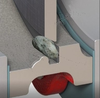
Figure 2. Hard debris in gate paths can cause electric actuators to trip before closure.
Increased torque. These valve types are long stroke valves, and stems tend to bend if lateral movement of the gate (which happens in knife gate valves during seating) is not isolated from the stem. Some valves use a rigid stem-to-gate connection (such as a slotted end stem) that provides no play, and it may cause stem bending. When a bent stem engages with the drive nut, operational torque increases. Designs with a stem-to-gate clevis that allows for little play is preferable.
Scaling, solidification and debris on stem threads caused by debris from the environment is another factor that increases operating torque. This is likely to occur considering the dirty environment in which most of these valves operate. Stem bellows and cover provide protection to the stem in such applications.
Most of these valves are designed to work well with minimal routine stem lubrication; however, total lack of lubrication may also make operation difficult.
Actuation issues. Insufficient air pressure to pneumatic actuators (due to air-line leaks, for example) can cause reduction in thrust for proper operation of the valve. Figure 2 shows a bi-directional perimeter seal slurry valve damaged by incomplete closure. In this case, it was caused by air supply to the actuator going low. Extensive damage is caused to the perimeter elastomer seal and the body by the abrasive slurry leaking at high velocity.
Some designs, like uni-directional valves with electrical actuators, are set to trip when a certain torque is exceeded, which happens when the valve is fully closed. However, a hard, large particle in the media coming in the way of the gate while the valve is closing could create a false torque trigger and cause the electric motor to stop, leaving the valve partly open.
Jamming. A variety of situations can cause these valves to jam and prevent proper operation and/or closing. Hard debris in a dead pocket in the body that does not allow the gate to close fully is a common problem. Scale formation on elastomer seal surface in perimeter seals can harden and prevent easy movement of the gate and/or create damage to the seal when forced.
Dewatering and media settlement or solidification in the body cavity also can cause jamming. Hard scaling, which is not easily dislodged on any mating parts (gate surface, stem threads, piston rod, seat, packing) creates the potential for jamming. Overtightening of the packing gland to arrest leakage can also cause the valves to jam.
Erosion in sealing areas. Partial closing and high velocity seat leakage of abrasive media through the narrow leak paths can highly accelerate wear of the sealing area and parts involved. In some situations, the valve could be made totally unserviceable within weeks or days. Usually for such applications, the recommended valve models will have the sealing parts hard faced or made of harder metals that can withstand the wear, even with the envisioned leakage.

Figure 3. Examples from user sites.
Body wear due to erosion is relatively less common. Most of these valves are full port designs that offer little resistance to flow from exposed body parts. However, seat leakage with abrasive media could also erode adjacent body parts, often drastically.
Improper selection/usage. Some erroneous usage causing field failures can be traced to deficiencies in the user’s knowledge of specific capabilities of these valve designs.
Using a uni-directional valve incorrectly with reverse pressure is rare, but when done can cause serious damage. Figure 1-photo 2 shows a uni-directional valve with a deflection cone that was accidentally subjected to reverse pressure in an abrasive slurry application. The slurry passed through the narrow gap between the gate and the cone causing damage to the gate in a circular area.
Use of a light-duty design in a demanding application that requires a heavy-duty model is quite common. Though done with a view to lower costs, this could lead to enhanced wear and/or premature failure, eventually resulting in higher costs.
Based on the details outlined above, here are some broad guidelines for improving operational ease and service life of these valves:
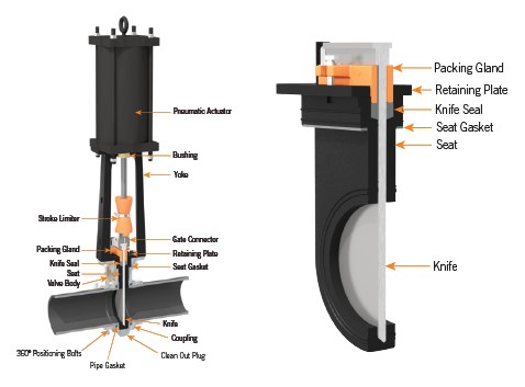
Figure 4. Replaceable seat cartridge. Photo credit: Courtesy of Victaulic
Knife gate and slurry valves, in general, are more expensive and less widely stocked compared to general purpose valves. Proper care of these valves in line with their anticipated failure modes and expected life can greatly reduce both inventory and plant shutdown costs.
The images in this article are used to illustrate typical valve failure instances; we acknowledge these images are from multiple sources who own them. The failures indicated are not restricted to the specific makes of valves in the photos. Identical failures can be found in similar designs from all manufacturers.
Dr. S. Vijayakrishnan spent most of his career with manufacturers of knife gate and slurry valves in application engineering, marketing and operations. In a career spanning 30+ years, he worked for DeZURIK and VAAS in their Indian operations and retired as the business unit head; post retirement, he worked for Bray as global product manager for knife gate valves. He has authored several articles on these products in international magazines. Reach him at vijykrishnan@gmail.com.


Why engineered mounting kits are critical to valve automation integrity.
April 7, 2026
Simple automations can create big gains on the shop floor.
April 3, 2026
Prevention can help operators avoid system damage and shutdowns.
March 30, 2026
