The Role of Valves in HAZOP Studies
Process hazard analysis (PHA) is required by U.S.
#controls #standards
One of the many PHA methodologies is the hazard and operability study (HAZOP). Hazard identification and “what-if” scenarios are high-level hazard identification methodologies. HAZOP is a systematic hazard identification methodology designed to identify hazardous events that could occur during operation of a facility that might be caused by deviations from design intent. In the study, the potential causes and consequences are identified, and a judgment is made as to whether additional design features should be incorporated to safeguard against identified scenarios.
HAZOP serves as one of the final safety reviews in the engineering design phase before the pre-startup safety review. It is a qualitative analysis focusing on operating facilities that involve hazardous chemicals such as using, storing, refining, petrochemicals manufacturing, moving, handling and others.
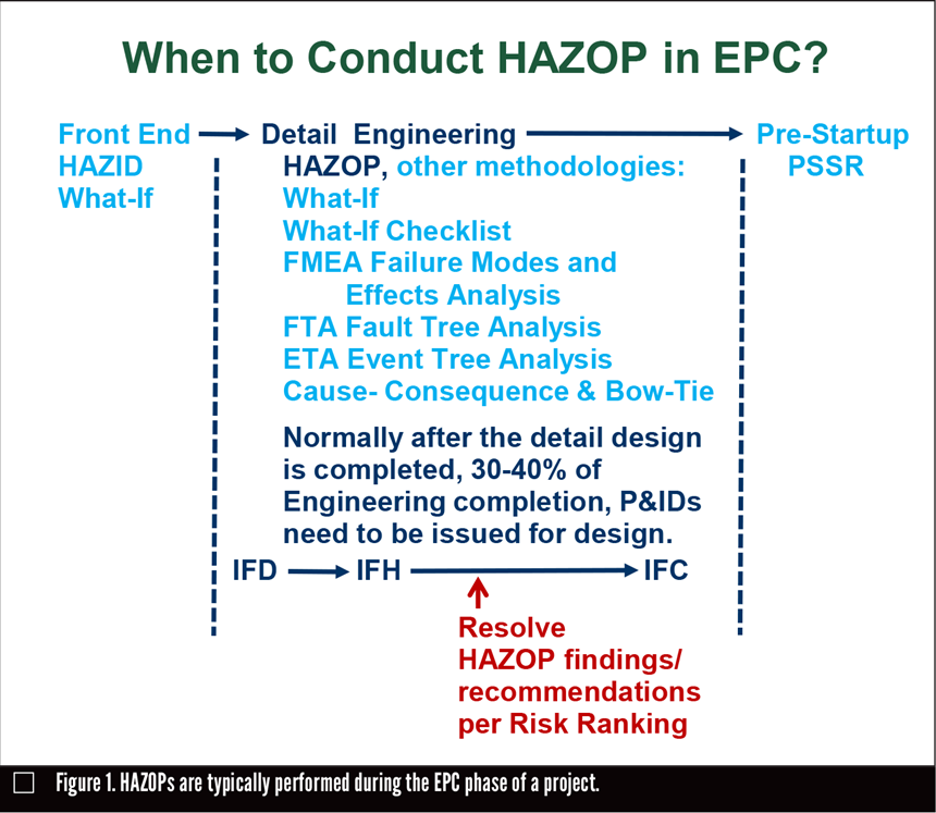
U.S. OSHA 29 CFR 1910.119 PSM states that the facility owner is responsible for performing and managing the HAZOP, which must be conducted by a team with expertise in engineering and operation. The initial HAZOP is conducted during the engineering, procurement and construction (EPC) phase of a project or facility planning (Figure 1). The required core members of this team are an independent facilitator, a technical recorder (scribe), at least one employee with operation experience and knowledge of the facility (operator), process engineers and controls/ instrumentation/electrical engineers. Other parties, such as mechanical and maintenance engineers, may also be included. The HAZOP is to be updated and revalidated at least every five years after the initial study is completed.
HOW THEY ARE CONDUCTED
The HAZOP can be conducted at the site or at the engineering office. The team works in an isolated, group setting where the engineers and operators evaluate the design to identify:
1. What could go wrong and the potential causes
2. Any hazardous events, previous incidents, etc.
3. Consequences for safety and the environment that would result, and the risk ranking for each consequence
4. Current safeguards in place, and what additional safeguards must be implemented to prevent an incident
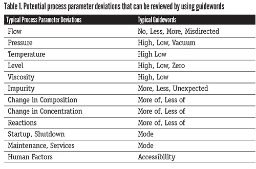
5. Systematic and structured reviews of selected operations or systems (nodes), and potential process parameter deviations—by using guidewords as shown in Table 1
6. Documented discussions in HAZOP worksheets, which may be assisted with available commercial software
ROLE OF VALVES
The role of valves in a HAZOP is very important. The HAZOP team only evaluates what could happen and what the consequences would be if the valves do not work properly or they fail to work as they are intended. Outside of the HAZOP, it is the valve experts’ and engineers’ responsibilities to figure out what might cause valves to fail the original design intent, as well as to come up with solutions to fix the potential problems in design.
The valves discussed in a HAZOP typically include the control valves and critical manual valves. The HAZOP team identifies and documents consequences when those valves fail the design intent.
For example, under “initiating causes,” the list would include:
- Flow control valve (FCV-xxx) fails open when required to be closed
- Flow control valve (FCV-xxx) fails closed when required to be open
- Pressure control valve (PCV-xxx) inadvertently closes
- Pressure control valve (PCV-xxx) inadvertently opens
- Manual valves (#xxx) inadvertently left open (e.g., after maintenance)
- Manual valves (#xxx) inadvertently left closed (e.g., after maintenance)
Many critical valves are in place for safety, which falls under “safeguards.” They include:
- Pressure relief valves for protecting pressure systems and equipment
- Blowdown valves for depressurization of critical vessels
- Emergency isolation valves (EIV) for isolating critical systems, equipment or inventories
- Check valves to prevent unwanted reverse flow
Supplemental questions related to valves may be asked to facilitate discussion of the team. Some typical questions excerpted from Guidelines for Hazard Evaluation Procedures, 3rd Edition are:
1. Can bypass valves (for control valves or other components) be quickly opened by operators? What hazards may result if the bypass is opened (e.g., reverse flow, high or low level)? What bypass valves are routinely opened to increase flow? Will properly sized control valves be installed?
2. How are the positions of critical valves (e.g., block valves beneath relief devices, equipment isolation valves, dike drain valves) controlled (by car seals, locks, periodic checks)?
3. Are critical isolation valve actuators powerful enough to close the valves under worst case differential pressure conditions (including backflow) in the event of rupture?
4. Are chain operators for valves adequately supported and sized to minimize the likelihood of valve stem breakage?
5. How are the positions of critical valves (e.g., EIVs, dump valves) indicated to operators? Is the position of all non-rising stem valves readily apparent to the operators? Do control room displays directly indicate the valve position, or do they really indicate some other parameter, such as actuator position or torque, application of power to the actuator or initiation of a control signal to the actuator?
6. Are block valves or double block and bleed valves required:
- Because of high process temperature? And/or pressure?
- Because the process material is likely to erode or damage valve internals?
- Because the process material is likely to collect on the valve seat?
- For worker protection during maintenance?
7. How will control valves react to loss of control medium or signal? Do the control valves:
- Reduce heat input (cut firing, re-boiling, etc.)?
- Increase heat removal (increase reflux, quench, cooling water flow, etc.)?
- Reduce pressure (open vents, reduce speed of turbines, etc.)?
- Maintain or increase furnace tube flow?
- Ensure adequate flow at compressors or pumps?
- Reduce or stop input of reactants?
- Reduce or stop makeup to recirculation system?
- Isolate the unit?
- Avoid over-pressuring of upstream or downstream equipment (e.g., by maintaining level to avoid gas blow-by)?
- Avoid overcooling (below minimum desired temperature)?
After the HAZOP review meeting, a HAZOP report is generated and filed. All the findings and recommendations of the team must be documented and resolved. As general practice for projects, HAZOP action items and recommendations are usually resolved before piping and instrumentation diagrams can be issued for construction.
HUMAN FACTORS ENGINEERING
The valve placement, orientation and location in the facility are the owners’ responsibility, not the valve manufacturers’, and all of those factors may impact safety. For this reason, manufacturers are expected to design and improve on a valve’s operability and user-friendly aspects.
ASTM F1166–07, Standard Practice for Human Engineering Design for Marine Systems, Equipment and Facilities provides ergonomic design criteria from a human-machine perspective for the design and construction of maritime vessels and structures, and for equipment, systems and subsystems.
ASTM F1166–07, Section 12, Valve Placement, Orientation and Location provides valve criticality information for a variety of valves. This information recognizes the importance and criticality of valves, which are classified by three categories:
Category 1 – Critical and essential for normal or emergency operations, safety and environmental reasons. These would:
- Be used frequently (at least once in a six-month period)
- Have a high likelihood of failure, or the consequence of failure or lack of quick access would be serious
- Be valves with handwheels or handles greater than 24 inches (610 millimeters) in diameter or length
Examples include: control valves, their bypass, isolation valves; relief and de-pressuring valves and emergency shutdown; trip and anti-surge valves; liquid cargo transfer valves for hydrocarbon.
Category 2 – Not critical for normal operations, but required for routine operations and maintenance. These would be used frequently (at least once in a six-month period).
Examples are: sewage treatment valves; condensate drain valves; service oil valves; potable water valves; ship service air valves; hydraulic service; frost gas valves; manual valves for normal startup/shutdown; drains and vents (1-inch) or less with flange and cap end.
Category 3 – Normally non-operating valves that are used in particular circumstances on an infrequent basis.
Examples are valves used in dry dock only for:
- Initial vessel or structure commissioning
- Decommissioning
- During startups after extended shutdowns
- During extended shutdowns
- Isolating pressure vessels, tanks, etc., for inspections
- Tie-in valves
- Pressure testing.
EMERGENCY ISOLATION VALVES
EIVs also play an important role in safety and environmental risk assessments. During a formal risk analysis, consequences and incidents are normally calculated based on inventory and on chemical and physical properties of the released hazardous material. Correctly placing EIVs in the process system can reduce the level of potential leaking during emergency situations. Failures of critical valves can lead to catastrophic failures.
Examples of important EIVs include suction valves in piping to pumps that are fed from large towers, accumulators or feed surge drums; isolation valves upstream of fire heaters, compressors and heat exchangers; and so forth.
In accordance with American Petroleum Institute (API) Recommended Practice (RP) 2218, valves that are potentially in a fire exposure scenario should be fireproofed for both the power and signal lines connected to the valve. The valve’s motor operator should be sufficiently fire-protected to provide enough time for the valve to fully open or close. Valves that fail to the safe position need not be fireproofed. However, they should be able to default to the fail-safe position when under a fire challenge.
CONCLUSION
To summarize, the role of valves in HAZOP studies and improving the safety and environment of plants is as follows:
All types of valves play an important role in the facility’s safety and environmental compliance. The risks are prevented or mitigated through engineering and valve design, construction of materials, selection, sizing, placement, etc. Key tools used in the design stage include:
- Early hazards identification at the detailed engineering phases can offer great opportunities for various engineering disciplines to apply inherent safer design principles or risk tolerable solutions to prevent or mitigate the potential safety and environmental hazards.
- Correct placement and selection of valves can reduce the size of spills and prevent or lessen the potential for catastrophic losses.
- Tight shutoff valve quality will ensure reduced downtime and improved revenue savings in the life of plants.
In formal risk analysis, the resulting consequence is normally calculated and based on inventory and chemical and physical properties of the released hazardous material. EIVs also play an important role in calculating the inventory and total potential leak quantities.
Li Li is senior health, safety and environment technical specialist for Fluor (www.fluor.com). Reach her at Li.Li@fluor.com.
REFERENCES:
1. United States Occupational Safety and Health Administration, 29 Code of Federal Regulation, Standard number 1910.119, Process Safety Management of Highly Hazardous Chemicals
2. Guidelines for Hazard Evaluation Procedures, 3rd Edition, Center for Chemical Process Safety (CCPS), published by CCPS/AICHE, 2008
3. ASTM Standard, Designation: F1166 – 07 (Reapproved 2013), Standard Practice for Human Engineering Design for Marine Systems, Equipment and Facilities
4. American Petroleum Institute Recommended Practice (RP) 2218, 3rd edition, July 2013
RELATED CONTENT
-
Proper Care of Knife Gate and Slurry Valves
How to resolve—and avoid—field failures of knife gate and slurry valves
-
The Biggest Valves: Sizes Growing in Step with Greater Demand
Valve manufacturers that have the expertise, skills, equipment and facilities to produce large valves are rare.
-
Testing of Hydrogen Valves
Valves are used to control all types of fluids, and while some are easy to manage, others can be a challenge. At the top of the challenging list sits hydrogen, the smallest, lightest molecule known to man.


 Unloading large gate valve.jpg;maxWidth=214)