Optimizing Valve Performance and Reliability with Remote Mount Technologies
As the interface between a valve and its control system, positioners play an important role in ensuring reliability and optimal performance in automated process plants.
#automation
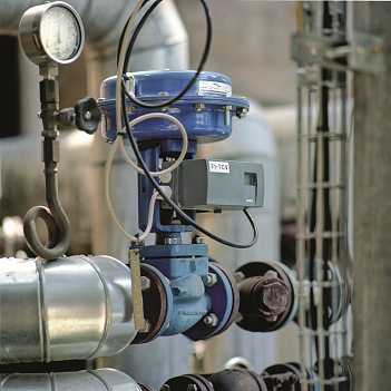
Additionally, many valves and positioners in process plants are exposed to harsh conditions, such as dust, moisture, high temperatures and vibration. These environments can impart excessive wear on the positioner and cause damage to sensitive electro-mechanical components, leading to increased maintenance requirements and a higher likelihood of unplanned downtime.
In both of the above scenarios, the use of remote mount technology can provide numerous operational and safety advantages. When it is coupled with digital monitoring capabilities that provide transparency into valve health and performance, end-users can transform the way they operate their plants by employing predictive maintenance strategies aimed at reducing costs and maximizing process uptime.
TYPES OF REMOTE MOUNT TECHNOLOGIES
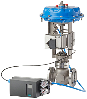
Remote mount position detectors, or remote detection units (RDUs) as they are sometimes called, can be used for both linear and part-turn actuators. Their primary advantage lies in the fact that the sensing feedback portion of the positioner is physically separated from the main control housing. The controller unit is fitted a certain distance away and is connected to the position detection system by an electric cable and to the actuator by one or two pneumatic lines. The sensing unit detects the position of the valve stem and transmits a feedback signal to the housing containing the electronics.
This design allows the operator to move electronic elements up to 120 feet (or further) away from the valve. Ideally, this would be to a location where they are not exposed to harsh conditions and can be safely and easily accessed by a technician. It also enables operators to mount multiple control housings close to one another, which makes monitoring and adjustment of valves throughout the plant quicker and easier.
Various types of RDUs and associated technologies are available depending on the specific valve application and location. Two of the most widely used technologies are high-resolution potentiometers and non-contacting sensors (NCS).
Potentiometers are three-terminal resistors that utilize a sliding or rotating contact to create an adjustable voltage divider or linear circuit in which the output voltage produced is a fraction of the input voltage. RDUs with potentiometers are optimal for very small linear actuators with a short valve stroke because the space required by the potentiometer is small. The transmission characteristic of the potentiometer is also optimal for small strokes.
Another notable benefit of the potentiometer is that a mechanical limit switch module can be installed inside of the remote housing.
Limit switches, either mechanical or proximity technology, are utilized to obtain valve limit detection that is independent from the positioner’s CPU. However, this can occur only if there is a mechanical connection to the movement of the valve stroke. The RDU utilizes a mechanical linkage to obtain its position signal, thereby allowing limit detection modules to be installed onto the same connection in a shared housing. This is in contrast to traditional setups, which require customers to accommodate mounting for two limit switches and the positioner. This shared housing for the RDU limit switch can offer egress protection and is available in multiple materials like polycarbonate and aluminum.
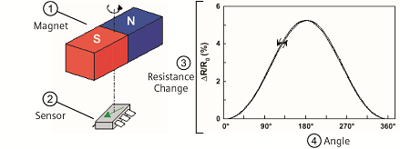
The second type of RDU utilizes NCS and operates on the giant magnetoresistance effect. As its name indicates, the RDU is non-contacting, making it an ideal fit for applications where high vibration or excessive mechanical wear is a concern.
In rotary applications, a magnet is affixed to the input shaft of the actuator. The NCS is positioned just above the magnet, within its magnetic field. As the magnet rotates, the resistance of the sensor changes, thus providing a change of resistance that is directly proportional to the actuator’s position.
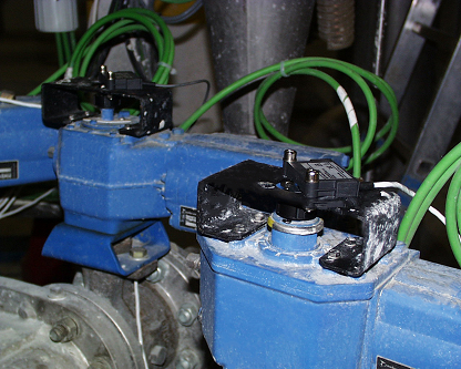
In small-stroke linear applications, on the other hand, the magnet is affixed to the actuator/valve shaft via a bracket. The NCS is secured to the actuator’s yoke arm. This places the sensor within the magnet’s magnetic field, with approximately 3 mm clearance. As the magnet moves in a linear direction, the resistance of the NCS changes, just as it does in the rotary application. In such cases, the valve travel is typically limited to about 14 mm (0.5 inches). To capture valve strokes longer than this, the rising stem motion can be converted to rotary.
In addition to built-in-technologies, third-party position sensors can also be utilized. In cylinder-type actuators, for example, position sensors can provide the necessary feedback signal via the electromagnetic compatibility (EMC) filter or analog input module (AIM) card. This eliminates the need for any type of mechanical linkage.
Linear displacement sensors can also be utilized. Typically, long valve stroke applications require extended feedback arm assemblies, which increase the valve’s installation dimensions. Linear sensors and their shafts are mounted in parallel with the valve movement, thus providing a position sensor signal that is directly proportional to travel and reducing the valve’s installation size.
Cable potentiometers, or “string pots” as they are sometimes called, can also be incorporated and are ideal for extremely long valve stroke applications (i.e., over 40 meters).
LEVERAGING DIGITALIZATION AND REMOTE DIAGNOSTICS
With valves and positioners, there is frequently great potential for optimization which, with the right information, can be exploited to improve the state of entire plants.
Faultless valves are essential for trouble-free processes in a chemical plant. In some cases, the failure of a single valve can halt production altogether. Sudden valve defects also pose a safety risk to employees. In order to prevent potential problems, plant operators must maintain their valves regularly. However, with limited data and visibility, this often leads to technicians performing work on valves that have no faults and are operating nominally, thereby driving up operating costs unnecessarily.
Leveraging digital technologies enables operators to transform their maintenance strategies by harnessing data to develop a predictive approach to service. The Siemens valve monitoring app, for example, collects and analyzes valve data to reduce maintenance costs and increase plant availability by tracking individually selectable key performance indicators (KPIs), such as shifts in the end positions of valves, friction indicators, number of valve strokes, etc.
Many of these predictive KPIs come standard with positioners. Integral pressure sensors also monitor compressed air supply and valve chamber pressure. Maintenance information on spring status, number of strokes, static friction affecting the gland seal, wear to the valve seat and alerts are also made available to operators in accordance with NE107.
This collection and analysis of data allows for more intelligent control of plant valves and translates into tangible benefits, including higher availability and avoidance of spontaneous valve defects, reduced maintenance costs through prioritized maintenance, increased transparency into valve and positioner health, detection of abnormalities and heavy wear, and reduced operating costs through optimized setting of positioners.
Savings can be magnified even further when data from multiple valves and even entire plants is collated in a virtual cloud. Doing so allows operators to apply advanced tools, such as artificial intelligence (AI) and machine learning to identify long-term performance trends and early indicators of failure. This knowledge can then be used to optimize valve operation at the enterprise level.
CONCLUSION – MAXIMIZING ROI
For continuous-process plants, uptime and efficiency are often highly contingent on the reliability and performance of hundreds of valves spread across the facility. Many of these valves are exposed to harsh conditions, such as high vibration and temperature, which can cause mechanical wear that results in a need for frequent maintenance. Other valves are located in hard-to-access locations that put service technicians at risk.
Remote mount positioners solve this problem by allowing operators to physically separate the valve assembly from the main control housing that contains highly sensitive electronics. Although these setups are often associated with a slightly higher up-front cost than conventional designs with the valve and positioner located in the same location, these costs can often be quickly recouped through better maintenance, fewer failures and optimized valve performance with data monitoring and digitalization.
Sean McNutt is product marketing manager at Siemens Industry, Inc.
RELATED CONTENT
-
The Rationale Behind Valve Characteristics
Back in the “early days,” we were taught that, to properly control flow, we should select a linear valve characteristic when the valve controls more than 25% of the piping system pressure drop at full flow.
-
Fugitive Emissions Standards for Valves
API, ISO and TA Luft all have their own set of standards to control emissions. What are the differences and how do they compare?
-
Ball Valve Basics
Welcome to the first in a series of Valve Basics articles, each focused on a major product type and written especially for newcomers to the industries that use and make valves and related products.


 Unloading large gate valve.jpg;maxWidth=214)

