A Case for Mechanical Temperature Control
Instrument, mechanical or project engineers may see a multitude of temperature applications cross their desks.
#controls #basics
When approaching a temperature control application, the engineer usually considers:
- The degree of accuracy needed
- Whether the application requires feedback (Are limit switches/output signals used?)
- Whether the application needs to be controlled through a DCS, PLC or other type of controller
- The budget for the application.
The answer to whether a mechanical temperature regulator might be a cost-effective and reliable solution for the application depends on those considerations.
In almost any process facility, a variety of temperature control applications can be found. As with any controlled variable, both the accuracy and criticality of those applications can vary widely. Often, non-critical temperature applications become instrumented control loops even when a self-operated or mechanical regulator could provide the desired accuracy along with a substantial cost savings.
WHAT’S CONSIDERED
- a temperature sensor
- wiring and conduit
- connection to a controlling device
- a control valve (and sometimes a positioner and/or I/P converter, and an air-filter regulator)
- plant air
A self-contained temperature regulator requires no power, no air supply or other expensive components to operate. Representative costs based on a 1-inch line size would be:
- Temperature transmitter: $300-1,000
- Temperature controller: $400-1,000
- Control valve and actuator: $1,500-3,000
- I/P converter: $200-350
- Air set regulator: $100-150
- Positioner: $500-2,000
- Control loop total: $3,000-7,500
- Temperature regulator: $500-2,500
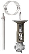
Although designs may vary from manufacturer to manufacturer, most temperature regulators operate on the same principle. A premeasured amount of “fill” is drawn into the thermal system filling the upper diaphragm chamber, the capillary tube and most of the bulb. As the controlled temperature increases, the fill in the sensing bulb begins to vaporize and creates pressure on the sealed system. This pressure drives the valve stem, closing direct-acting valves or opening reverse-acting valves. By using different fill fluids, many different temperature control ranges can be offered for both cooling and heating applications—temperature ranges are readily available from -20° F (-29° C) to 500° F (260° C).
Applications for which these devices might be ideal include tank farms, large heat exchangers, heat exchangers with slow temperature changes, area heating/cooling (warehouse/maintenance shops) and steam tracing.
As could be expected, temperature regulators do not react as quickly as control loops, and these regulators will have a broader temperature band versus setpoint. To accomplish full travel, a span of 8 to 20 degrees is typical. However, when applied correctly, accuracy of 3 to 4 degrees can be expected at plus or minus the desired setpoint. It is up to specifiers to decide if such a temperature band is acceptable.
They will also need to consider whether there is a need for stem position or temperature feedback. A mechanical device typically has no output signal or position switch to give the operator field visibility.
Certain steps can be taken to maximize the accuracy of the temperature application. Considerations in regards to that issue include the temperature range of the actuator, the stroke length of the valve (a shorter stroke requires less fill fluid phase change to stroke the valve, thus improving performance), and the installed flow capacity (Cv) in the valve body.
Additionally, many manufacturers offer piloted temperature regulators that provide reduced temperature spans and, in many cases, larger line sizes for higher flow rates.
SENSING ELEMENTS
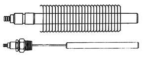
“Dead zones” toward the capillary end of a bulb often are used to ensure temperature reading is in the desired area of a tank or vessel (Figure 2).
Many customers will use a thermowell to facilitate installation and maintenance tasks.
STEAM TRACING
Stories abound of burst water lines that occur when plants experience an early freeze. This often results from steam tracing lines not used because an operator either fails to open the necessary steam tracing valves or is not aware of a weather forecast. Fortunately, products are available that can eliminate this issue.
With steam tracing water lines, both the bulb and capillary often can be eliminated and the actuator allowed to simply measure and react to the ambient temperature. Using the example of the burst water line above, an operator could set the temperature regulator for 40° F (10° C), thus ensuring the valve will begin to open once the temperature drops below that setting. Once the valve opens, steam will begin to flow to the tracing lines, minimizing the risk of freezing the water within the piping. Such valves not only reduce the likelihood of human error, they also provide dramatic utility cost savings. The same valve that opens at 40° F (10° C) will then close as the ambient temperature rises above that level so costly steam will not be allowed to flow into tracing lines when not needed.
As with any industrial product, quality and accuracy of temperature regulators varies from manufacturer to manufacturer. When selecting a valve for this purpose, considerations should be:
- Is the thermal system fully sealed and replaceable?
- What is the manufacturer’s stated accuracy?
- What “real world” accuracy can be expected?
- Is the application suitable for a commercial or industrial valve?
INSTALLATION AND MAINTENANCE
Understanding the cost advantages of a self-contained temperature valve is easy—both at the component level and with installation labor costs. What’s a little more complicated is troubleshooting issues. When a temperature control failure in a control loop occurs, multiple devices may be responsible and troubleshooting involves seeking out the component causing the error. If a mechanical valve is used, an operator simply checks the setpoint on the valve for accuracy. If that setpoint is correct, the thermal system is tested. Components not working correctly can be replaced. If testing proves the valve is functioning, the heating/cooling fluid supply is checked.
CONCLUSION
Mechanical temperature regulators can provide a cost-effective and reliable means to control temperature. When they are appropriate for an application, they also can simplify maintenance and reduce both installation and operating costs.
TIM GAINER is a regional manager for Jordan Valve (www.jordanvalve.com) in Cincinnati, OH. He has been part of the Jordan Valve team for over 15 years and has nearly 20 years of control valve and regulator experience. Reach Gainer at tgainer@richardsind.com.
RELATED CONTENT
-
Solenoid Valves: Direct Acting vs. Pilot-Operated
While presenting in a recent VMA Valve Basics 101 Course in Houston, I found myself in a familiar role: explaining solenoid valves (SOVs) to attendees. (I work with solenoids so much that one VMA member at that conference joked that I needed to be wearing an I Heart Solenoids t-shirt). During the hands-on “petting zoo” portion of the program, which involves smaller groups of attendees, one of the most frequently asked questions I get from people came up: What’s the difference between direct-acting and pilot-operated SOVs, and how do we make a choice?
-
Flow Control Valves: Common Problems and Solutions in Energy
When systems are operating optimally, they can improve productivity, lower operating costs, increase reliability, reduce emissions and enhance safety.
-
New Technologies Solve Severe Cavitation Problems
An advanced anti-cavitation control valve design enabled by 3D metal printing solved a power plant’s severe cavitation problem and dramatically improved its bottom line.


 Unloading large gate valve.jpg;maxWidth=214)