
Produced by


Published August 9, 2023
High pressure, high-temperature applications require a safe, leak-free pressure-containing boundary.
By Don Bowers
When I look back at the original article, Pressure Seal Valves: Simple Designs, Demanding Applications (published previously by VMA in Valve and included in Back to Basics, originally published in 2009), I am struck with how much has remained constant from a design and applications standpoint in the realm of large diameter (4-inch and greater), high pressure/temperature pressure seal gates, globes and checks. Whereas metal seated ball valves have displaced pressure seal gates and globes in a number of applications, plant designers still choose pressure seal, parallel slide gate valves for main steam isolation (stops) in combined cycle power plants and in other similar applications. Where steam throttling is required, pressure seal globes are specified, and where reverse flow protection is necessary in high-energy piping systems, pressure seal check valves are installed.
Design Advantages: I always like to kid valve designers that we valve guys are not overly creative in our nomenclature. The term “pressure seal” is no exception. These valves use system “pressure” to “seal” that pressure from the environment. In the case of a standard 150-600# bolted bonnet gate/globe/check valve, having a flanged body-bonnet joint sealed by a gasket; as system pressure increases, so does the potential for leakage. In the pressure seal design, as system pressure increases, the potential for leakage decreases. Besides having this advantage, most pressure seal designs weigh less than their bolted bonnet counterparts as a function of the combined incremental weight of the body and bonnet flanges, as well as the connecting nuts and bolts.
Although many of the design considerations have remained fairly constant, there are several advances that have driven change to the pressure seal valve.
These advancements work together to provide manufacturers with the tools to create better quality pressure seal valves quicker. Whether in a power plant, a refinery, a chemical plant, an aircraft carrier or a pulp and paper mill, pressure seal valves installed in high-ressure/temperature applications continue to provide excellent service for their owners.
Relying on fairly simple design principles, pressure seal valves have proven their capability to handle increasingly demanding fossil and combined-cycle steam isolation applications, as designers continue to push boiler, HRSG, and piping system pressure/temperature envelopes.
Pressure seal valves are typically available in size ranges from 2 inches to 24 inches and ASME B16.34 pressure classes from #600 to #4500, although some manufacturers can accommodate the need for larger diameters and higher ratings for special applications.
Keeping pace with advancements in material technology, today’s pressure seal valves are available in carbon (A105 forged and Gr. WCB cast), alloy (F22 forged and Gr. WC9 cast; F11 forged and Gr. WC6 cast), austenitic stainless (F316 forged and Gr. CF8M cast; for over 1000° F, F316H forged and suitable austenitic cast grades with carbon content > 0.04%), as well as a number of other alloy/stainless/special materials. Also available from most manufacturers is the F91 forged and/or C12A cast alloy (9 Cr-1 MoV) material used for high-temperature (e.g. main steam) piping systems in the last round of combined-cycle power plant construction and newer coal-fired super- and ultra-supercritical units.
The pressure seal design concept can be traced back to the mid-1900s, when, faced with ever-increasing pressures and temperatures (primarily in power applications), valve manufacturers began designing alternatives to the traditional bolted-bonnet approach to sealing the body/bonnet joint. Along with providing a higher level of pressure boundary seal- ing integrity, many of the pressure seal valve designs weighed significantly less than their bolted bonnet valve (BBV) counterparts.
Bolted Bonnets vs. Pressure Seals
To better understand the pressure seal design concept, let’s contrast the body- to-bonnet sealing mechanism between BBVs and pressure seals. Figure 1 depicts the typical BBV. The body flange and bonnet flange are joined by studs and nuts, with a gasket of suitable design/material inserted between the flange faces to facilitate sealing.
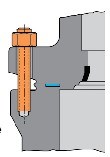
Figure 1
Studs/nuts/bolts are tightened to prescribed torques in a pattern defined by the manufacturer to affect optimal sealing. However, as system pressure increases, the potential for leakage through the body/bonnet joint also increases.
Now let’s look at the pressure seal joint detailed in Figure 2. Note the differences in the respective body/bonnet joint configurations. Most pressure seal designs incorporate “bonnet take-up bolts” to pull the bonnet up and seal against the pressure seal gasket. This in turn creates a seal between the gasket and the inner diameter (I.D.) of the valve body. A segmented thrust ring maintains the load. The beauty of the pressure seal design is that as system pressure builds, so does the load on the bonnet and, correspondingly, the pressure seal gasket. Therefore, in pressure seal valves, as system pressure increases, the potential for leakage through the body/bonnet joint decreases.
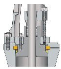
Figure 2
This design approach has distinct advantages over BBVs in main steam, feedwater, turbine bypass, and other power plant systems requiring valves that can handle the challenges inherent in high-pressure and temperature applications. However, due to its reliance on system pressure to aid in sealing, pressure seal valves are best applied in systems where the minimum, consistent operating pressure is in excess of 500 psi.
But over the years, as operating pressures/temperatures increased, and with the advent of peaking plants, this same transient system pressure that aided in sealing also played havoc with pressure seal joint integrity.
Pressure Seal Gaskets
One of the primary components involved in sealing the pressure seal valve is the gasket itself. Early pressure seal gaskets were manufactured from iron or soft steel. These gaskets were subsequently silver-plated to take advantage of the softer plating material’s ability to provide a tighter seal. Due to the pressure applied during the valve’s hydrotest, a “set” (or deformation of the gasket profile) between the bonnet and gasket was taken. Because of the inherent bonnet take-up bolt and pressure seal joint elasticity, the potential for the bonnet to move and break that “set” when subjected to system pressure increases/ decreases existed, with body/bonnet joint leakage the result. This problem could be effectively negated by utilizing the practice of “hot torquing” the bonnet take-up bolts after system pressure and temperature equalization, but it required owner/user maintenance personnel to do so after plant startup. If this practice was not adhered to, the potential for leakage through the body/bonnet joint existed, which could damage the pressure seal gasket, the bonnet and/or the I.D. of the valve body, as well as creating compounding problems and inefficiencies that the steam leakage could have on plant operations.
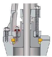
Figure 3
As a result, valve designers took several steps to address this problem. Figure 3 shows a combination of live-loaded bonnet take-up bolts (thus maintaining a constant load on the gasket, minimizing the potential for leakage) and the replacement of the iron/soft steel, silver-plated pressure seal gasket with one made of die-formed graphite. The gasket design shown in Figure 3 can be installed in pressure seal valves previously supplied with the traditional type gasket. Figure 4 shows another design approach accomplishing the same end result.
The advent of graphite gaskets has further solidified the dependability and performance of the pressure seal valve in most applications and for even daily start/stop operating cycles. Although many manufacturers still recommend “hot torquing,” the potential for leakage when this is not done is greatly diminished.
The seating surfaces in pressure seal valves, as in many power plant valves, are subjected to, comparatively speak- ing, very high seating loads. Seat integrity is maintained as a function of tight machining tolerances on component parts, means of providing the requisite torque to open/close as a function of gears or actuation, and selection/ application of proper materials for seating surfaces. Cobalt, nickel, and iron-based hardfacing alloys are utilized for optimal wear resistance of the wedge/disc and seat ring seating surfaces. Most commonly used are the CoCr-A (e.g., Stellite) materials. These materials are applied with a variety of processes, including shielded metal arc, gas metal arc, gas tungsten arc, and plasma (transferred) arc. Many pressure seal globe valves are designed having integral hardfaced seats, while the gate valve and check valves typically have hardfaced seat rings that are welded into the valve body.
Valving Terminology
If you have dealt with valving for any length of time, you’ve probably noticed valve manufacturers are not overly creative with the terms and vernacular used in the business. Take for example, “bolted bonnet valves.” The body is bolted to the bonnet to maintain system integrity. For “pressure seal valves,” system pressure aids the sealing mechanism. For “stop/check valves,” when the valve stem is in the closed position, flow is mechanically stopped, but when in the open position, the disc is free to act to check a reversal of flow. This same principle applies to other terminology used for design, as well as valve types and their component parts.
Pressure seal gate valves basically come in two types:
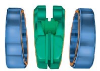
Figure 4
1. Flex-wedge type gate valves (Figure 4) incorporating a flexible, wedge-shaped closure element that, relying on the torque generated by the hand-wheel or motor operator, is driven into the seats of the valve, thus effecting sealing. The flex-wedge gate valve is said to be “torque seated,” because it relies on this applied torque to provide the sealing force, as well as some assistance from system pressure. This flexibility comes from the design of the wedge, where material is removed either by saw cutting or other processes inherent in forming/manufacturing, concentrically around a central hub. The increased flexibility allows for:
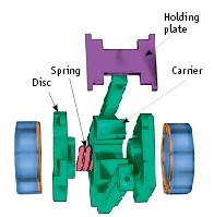
Figure 5
Other designs are available including “two-piece” and “double-disc” wedge types that have proven to be effective.
Which Valve to Use?
So why choose one over the other? Parallel slide valves rely almost entirely on upstream pressure to affect a seal on the downstream seat. Because of this, at low-pressure conditions, leakage through the seat may occur. In addition, the sliding action of the seating surfaces is more prone to wear, and if particulate is trapped between the seating surfaces, damage is more likely to occur. Due to the width and orientation of the seats, parallel slide valves are more difficult to maintain than their flex-wedge counterparts. But before you replace all your parallel slide valves with flex-wedge gates, read on.
Because the flex-wedge gate valve requires torque to energize the sealing surfaces (and then “un-wedge” itself), an actuator capable of providing comparatively higher torques (to parallel slide valves) is required, usually at a higher cost. Then there’s the thermal binding issue.
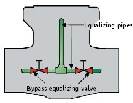
Figure 6
At operating temperatures approximating 800°F and higher, wedge-type gate valves have the potential to bind in a variety of modes (e.g. when exposed to high operating temperatures, closed, then allowed to cool; or as is common in startup, beginning at ambient temperatures, exposed to a rapid thermal transient, then opened). This phenomenon is dependent on a wide variety of design and operating conditions, but can be mitigated by incorporating operating procedures that verify thermal equalization between the upstream and downstream bores (delta T of 200°F or less). Bypasses (Figure 6) connecting the valve upstream and downstream bores can facilitate this thermal equalization. Care must be taken to verify upstream vs. downstream thermal equalization at the valve itself, not away from the valve on connecting pipe. The new generation combined-cycle plants with their comparatively (with coal-fired plants) fast startup procedures are particularly susceptible to thermal binding. However, the most effective way to guard against thermal binding is to choose the parallel slide design.
If you recall, in the parallel slide design (Figure 5), the two discs are held apart in the cage by a spring(s). This spring(s) allows the discs more than enough travel to exceed the effects of thermal expansion.
Thermal binding is not endemic to pressure seal valves. However, because pressure seals are routinely used in high-temperature service, take special care when addressing this issue.
Other Operating Concerns
In addition, users of pressure seal valves must address two related operating concerns: center cavity over pressurization (CCOP) and pressure locking. Like thermal binding, these phenomena can result in an inability to stroke the valve. Note that thermal binding, CCOP, and pressure locking are three distinct concerns, the potential of which must be carefully evaluated and addressed in the design/ procurement phase of the project. Paragraph 2.3.3 of ASME B16.34 places the responsibility on the owner to determine the potential for, and provide a means to protect against, CCOP and pressure locking.
The closure element of double-seated valves (wedge gates, parallel slide gates, ball valves, etc.) may become locked in place by either a buildup of pressure in the center cavity (CCOP) or an increase in the differential pressure upstream, downstream, or both of the seats in a closed valve as a function of decreased line pressure (pressure locking). In the case of CCOP (Figure 8), fluid trapped in the center cavity at ambient temperatures will expand when heat is introduced (e.g., during startup). This will cause the fluid to expand and, depending on the fluid type and temperature, could reach a pressure where insufficient torque is available (manually or actuated) to overcome the pressure and open the valve.
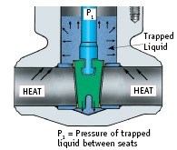
Figure 7
Pressure locking (Figure 7) occurs in double-seated valves where the line pressure drops (as a function of plant operation or accident) on either the upstream, downstream, or both sides of the valve seats, creating a sufficient differential pressure to preclude opening the valve.
As in thermal binding, there are several methods to guard against CCOP and pressure locking. These include the following:
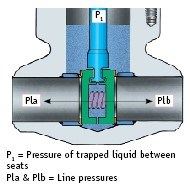
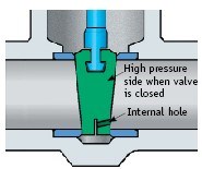
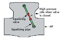
Figure 11
overpressure to that pressure side. This effectively makes the valve unidirectional in its sealing capability (Figure 9).
tapped into the valve’s center cavity. This method maintains the valve’s bi-directional sealing capability (Figure 11).
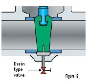
A drain valve that is connected to a pipe drilled and tapped into the valve’s center cavity (Figure 12). Remember that when the drain valve is closed, center cavity pressure is not being relieved.
Proprietary bypass valves that change sealing direction as does system pressure. Bi-directional sealing is maintained (Figure 13).
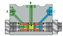
Figure 13
Pressure Seal Globe Valves
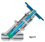
Pressure seal globe valves are utilized in applications where some degree of flow control (or throttling) may be required (e.g., in plant startup or shutdown modes). They are well suited for isolation applications in power plants (e.g., main steam isolation, feedwater heater isolation, boiler/economizer isolation, etc.). Pressure seal globes may be supplied in the same material types, actuation varieties (manual, gear operated, motor operated, pneumatic, electrohydraulic, etc.), trim combinations and materials, and ASME pressure classes as their gate valve counterparts. They can be supplied in a stem vertical (Figure 14) or inclined (Y-pattern) orientation (Figure 15), as a function of required flow (Cv). Pressure seal globes may be supplied with the disc mechanically affixed to the stem so that, when in the open position, flow is free to occur. However, they may also be supplied with the stem freely floating in the disc pocket (see inset, Figure 15). In this orientation (stop/check), when the valve is in the open position, the valve disc will close when a reversal of flow occurs, thus providing a check valve function in addition to the basic stop (or isolation) function.
The profile of the disc in globe valves may be modified to more finely control the amount of flow at operating conditions (Figure 16). This is particularly useful in throttling applications where the system is dependent on flow control to optimize performance. Scales may be affixed to the valve topworks to measure the valve stroke, which can be correlated to flow curves to accurately control the actual flow through the valve. Where tighter control such as modulating is required — and where consistent throttling at less than 20% open is expected — control valves, which incorporate valve operating systems designed for the application, are recommended. It is common to include an equalizing pipe to the non-pressure side to help balance the valve, increase lift, and control turbulence.
Figure 16
Pressure seal globe valves are not subject to CCOP, pressure locking, or thermal binding; however, the effects of high temperature (e.g., thermal expansion) must be evaluated on component parts (stem, seats, etc.), especially when the valve is to be actuated.
Pressure Seal Check Valves
The primary responsibility of pressure seal check valves is to seal against a system flow reversal, thus protecting piping and components (pumps, instruments, etc.) not designed to handle that condition. They are supplied in the same materials, pressure classes, and orientations (vertical and inclined) as pressure seal globe valves. Selection of check valves is typically based on a number of variables, including system flow characteristics (e.g., Cv, velocity), media (e.g., type and size/concentration of particulate), and plant operating characteristics.
Pressure seal check valves may be supplied in configurations, as follows:
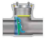
Figure 17
1. Swing Check (Figure 17). Pressure seal swing check valves are commonly used in combination with gate-type isolation valves for reverse flow protection. Their relatively higher Cv (vs. piston checks), simple operation, and relative ease of maintenance make them popular among piping system designers.
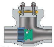
Figure 18
2. Tilting Disc Check (Figure 18). Due to a shorter moment between the hinge pin and centerline of the disc (vs. swing checks), tilting disc check valves can react quicker to reversals in flow, thus providing a higher margin of safety to the upstream equipment and media “hammer” potential. Note the differences in cost and Cv between these two common types of check valves before purchasing.
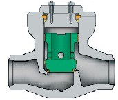
Figure 19
3. Piston Check (Figure 19). Pressure seal piston check valves are frequently used in conjunction with globe-type isolation valves for reverse flow protection. These valves are sometimes supplied with springs to aid in closing and/or equalizing pipes to aid overall performance.
Summary
Although similar to their ancestors in concept, today’s pressure seal valves have evolved to address a wider range of applications while delivering higher performance levels. Valve manufacturers continue their work in tweaking the various design elements contributing to pressure seal valve performance in order to provide greater value to the end user, thus assuring the key role that these valves will continue to play in power plant operation.
This article was originally published by VMA and written by Don Bowers Jr. when he was the director of sales, power, at Velan. All images are copyright of Velan, and some of the technology described within may be proprietary to the company. Minor updates have been made for this republication.


June 5, 2026
Why engineered mounting kits are critical to valve automation integrity.
April 7, 2026
Simple automations can create big gains on the shop floor.
April 3, 2026
