Lifecycle Management of Pressure Relief Valves
Accurately specified and appropriately maintained pressure relief valves (PRVs) are critical to protect plant personnel and equipment against unexpected overpressure events.
#pressure-relief #automation
PRESSURE RELIEF VALVES DEFINED
The term pressure relief valve is used as a generic all-encompassing term including relief, safety and safety relief valves. However, there are specific definitions associated with the opening action of specific styles of valves. It is important that the correct style of valve be applied to the specific process needs. This is especially significant in the case of liquids and “multi-phase” applications.
There are several types of pressure relieve valves, each with different levels of complexity and maintenance needs:
- Weight-Loaded PRV
- Conventional Direct Spring-Loaded PRV (ASME recognized)
- Balanced Direct Spring-Loaded PRV (ASME recognized)
- Pilot Operated PRV (ASME recognized)
The importance of PRVs is highlighted in the National Board Inspection Code, Part 2, 2.5.1. “The most important appurtenances on any pressurized system are the pressure relief devices provided for overpressure protection of that system.” They may never be called upon to operate, but when needed, must operate in a very specific manner. They are the last line of defense in an over-pressure event and protect employees and equipment.
Because of their importance to safety, PRVs are a diverse range of solutions found in several facets of a single operation, from steam boilers to low-pressure tanks, that can quickly add up in maintenance costs. For example, a typical 250,000 barrels per day refinery has thousands of PRVs with an annual maintenance cost that can easily exceed $2.5 mil USD. The actual direct costs to repair a PRV normally are relatively low compared to other equipment, but their downtime is critical since operation may not resume without proper overpressure protection.
PRVs are mostly self-operated mechanical equipment that do not depend on any control system or electrical instrumented system to function. Therefore, it is not possible to monitor relief event history or access online diagnostic information. Preventive maintenance with pre-scheduled inspection and testing is mandated to ensure functionality on demand.
DESIGN AND SPECIFICATION
PRVs are designed based on the general construction rules and operating conditions of the vessel or system which they protect. For instance, in most cases the PRV is set to open (within a defined tolerance) at the maximum allowable working pressure (MAWP) of the vessel. In addition, the PRV must flow its fully rated capacity before the pressure reaches the allowable accumulation of the vessel and must re-close (blow-down) before the pressure degrades below the normal operating pressure of the system.
In certain scenarios, such as multiple PRV installations and fire sizing, valves can be set higher than MAWP and may also be sized for full flow above the maximum accumulation.
Some of the common dimensional characteristics of a PRV include the size and pressure rating of the inlet and outlet as well as the size of the nozzle bore. For some styles of valves, these bore sizes carry a letter designation symbolizing minimum bore size adhering to industry standards. The combination of the area of the valve bore plus the dimensional lift of the valve when open, determines the amount of process fluid the valve will flow.
These standards may also standardize center-to-face dimensions, which allow end users to interchange PRVs from different manufacturers. Although overall height is not normally addressed by standards or recommended practices, it may be an important consideration in piping design and in replacement valve applications.
PRVs are designed, sized, selected and manufactured to meet requirements of specific codes and standards and are of special interest to the many jurisdictions charged with enforcement of local laws and regulations.
CODES AND STANDARDS
ASME Code Symbol Stamps are issued to companies meeting all requirements of ASME construction code relating to PRVs. In general, Section I valves are used on direct-fired boilers used for steam generation and power production. In the Oil and Gas Industry Section I, valves may be found in applications such as refinery boiler plants and oil field steam injection systems.
The majority of PRVs utilized by the Oil and Gas Industry are built to the requirements of ASME Section VIII for use on “unfired vessels” and may be found in virtually every aspect of the industry.
The “V” (Section I) and “UV” (Section VIII) symbols may be applied by either a “Manufacturer” or and “Assembler.”
The National Board of Boiler Inspectors (NBBI) acts as the authorized agency for ASME to perform several activities related to PRVs. The ASME test standards are also used for certified repair programs such as the NBIC “VR” program.
The NBBI provides certification for and operated their own certified lab for capacity certification of new PRV products. In addition, these labs are used for the re-certification of ASME manufacturers and assemblers as well as VR repair certificate holders.
The primary intent of the VR program is to ensure that a VR-repaired PRV is repaired to the same standards as the original code of construction.
A major difference in the ASME and VR programs is that while an ASME certificate holder is certified to build specific capacity certified models, a VR repair organization is certified to repair valves by section of the ASME code, testing fluid and other related activities (i.e. welding, machining… etc.). A VR Certificate holder may be certified for field repair, shop (depot) repair or both.
Although ASME is the most common standard to which pressure vessels and PRVs are manufactured, many other certifications exist. In most cases, these are based on geography and in some countries specific certifications may be required in place of or in addition to ASME. Some certification standards may be based on industry or type of application.
TOTAL COST OF OWNERSHIP
The total cost of ownership of a PRV, which includes the initial product cost like engineering, sizing, selection and commissioning, is the tip of the iceberg. Below the water line are all the hidden costs such as direct PRV repair labor, PRV repair parts, administrative, record keeping and other transactional activities, transportation, inventory administration, rigging/scaffolding/pipefitting, etc. Deeper yet is the cost of non-conformance such as unplanned outages, late delivery of repair valves, misapplication of PRVs, emissions, inventory utilization and incorrect maintenance intervals.
The initial purchase cost of a PRV is relatively low. However, due to the potentially large number of PRVs at any given site, the costs associated with record keeping and repair order placement can be substantial, especially if the valves were incorrectly selected or sized from the start. Typical maintenance cycles are from three to five years, and it is not unusual for a single repair cycle cost to exceed the original purchase price of the valve. There may also be considerable costs involved with accessing or retrieving PRVs for testing, inspection or repair. Costs escalate when valves are sent off-site for repair or decontamination.
OPTIMIZING PRVS THROUGH ASSET MANAGEMENT
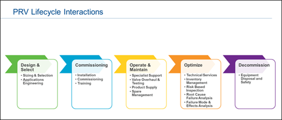
Physical assets have a life: they are planned and created, used, managed and maintained, and when no longer required prepared for disposal. From the day a PRV is sized and selected until it is finally retired from service, appropriate decisions must be made to ensure their safety and function, specifically regarding the valve maintenance program or asset management. Asset management is the strategic management of these valves during their life in the organization. PRV asset management optimization can reduce cost and increase reliability, while also minimizing unplanned shutdowns and loss of production (see Figure 1).
SIZING
It is essential to know and understand valve theory and applicable codes as they pertain to sizing and selection. PRV types, capabilities and constraints must be considered when sizing pressure relief valves and close communication between the PRV supplier, end-user and engineering firm is also essential. Although excellent sizing software is available, sizing should only be done by experienced, well trained, technical personnel.
When sizing and selecting the proper relief device, a determination must be made as to what event you anticipate may cause the over pressure event. In some instance there may be more than one possible cause. In those cases, you need to plan around the worst possible scenario which may involve more than one event occurring at once. Some examples of overpressure scenarios are: blockage discharge; external fire; tube rupture in heat exchanger; thermal expansion; runaway reaction; power failure; and overfilling storage vessels.
The primary factors when sizing a PRV are set point and flowing capacity. Temperature, composition of process fluid or gas, piping arrangements including existing flange size, dimensional restrictions, back pressure, operating ratios, materials of construction and preferred operating style of valve (pop or modulating…) are among other factors to be considered.
IMPROPER INSTALLATION
This can have serious consequences and will cause operational problems for years. Some common installation issues include incorrect inlet piping, restrictive outlet piping, the valve is mounted horizontally, back pressure is unknown at time of sizing, or there is an incorrect style of block valve at the PRV inlet.
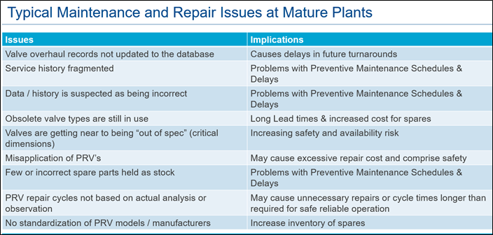
Once the valve is installed, proper PRV asset management can reduce costs while increasing reliability. Issues and implications of not managing those assets are seen in Figure 2.
BENEFITS OF VALVE ASSET MANAGEMENT
Management of valve data
Asset management data is a useful tool that can indicate adverse system operational characteristics of a process and provide evidence of poor valve performance. This data can also highlight the need for spare valves in problem applications that can ultimately reduce the downtime during repair outages and installation costs.
Proper asset data records include correct location of valves, identification and records of past service and tracking of future maintenance dates. Valve overhaul data will show past overhaul data for future diagnostics, provide details of job performed, real time status of valves in repair and track parts that need to be replaced at next overhaul.
Risk-based Inspection (RBI) is a risk assessment and management process that reduces risk by focusing inspection on the components that need more attention based on probability of failure and consequence of failure. Failure modes and probability of failures are calculated based on past performance and condition. Consequence of failures are calculated based on potential serious injury to employees, equipment damage, loss of production and repair costs caused by the failure.
An asset management program can enable RBI by properly maintaining historic records and generating inspection reports with recommendations for adjustments in a PRV maintenance cycle. Some PRVs may require an increase on their maintenance frequency. However, RBI can reduce cost by extending the average inspection frequency for the entire plant while reducing risk.
Root Cause Failure Analysis (RCFA) is a maintenance troubleshooting method to logically identify the causes behind the PRV failure. It is a very useful tool for improving the reliability by eliminating non-conformance and preventing re-occurrence. It is used in conjunction with RBI to set repair frequency of the PRVs.
Failure Mode and Effects Analysis (FMEA) activities are designed to recognize potential failures, evaluate the effects of potential failures in the process and identify the actions that could eliminate or reduce the chance of the potential failure occurring.
The objective of FMEA activities are to enhance the operating performance of the PRVs and minimize failure. FMEA offers greater assurance of PRV safety and performance.
Having this data allows efficient management of internal workflows for valve service. It also enables institution of a preventive/planned maintenance system and an inventory management system.
For operators, this means improved valve reliability and uptime, optimized maintenance planning, resourcing and spending and increased availability of needed parts while improving safety.
Managing and Optimizing PRV Spare Pools
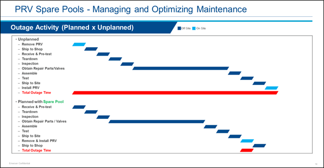
To reduce the costs of maintaining PRVs and the associated inspection and testing activities, many end users have found using spare PRVs as an effective strategy. Redundant valves are purchased mirroring the installed PRVs and then kept in storage ready for quick exchange when the installed PRV is removed from service. Using this strategy can allow PRVs to be prepared for installation well in advance of planned STO (Shutdowns, Turnarounds, and Outages) and minimize and simplify the work to be performed during the outage (see Figure 3).
Implementing a spare pool also helps minimize the time employees are exposed to possible safety hazards involved working on scaffolding, etc., while performing the removal and installation work. After the in-service PRV is removed from the site, it is returned for inspection and refurbishment to the spare “pool” where it can be used in a future STO cycle.
When plants have at least some spare PRVs to back up their installed assets, it is important to have a program that can be optimized to make the use of those assets more efficient and reduce both risk and maintenance costs. The key to optimizing a spare pool program is understanding the makeup of the installed PRV base across all operating units in the plant, identifying which PRVs can be used as part of a general pool and which are critical or special PRVs which might require a higher level of back up to mitigate against the costs of any unplanned service events.
“Like for like” sparing of installed valves. Although one of the less flexible and more costly strategies, it does offer immediate back up for installed PRVs and is often used for critical valves. In some cases, the customer may use a “twin” installation such as a Safety Selector Valve allowing for permanent installation of the spare and active PRV.
CONCLUSION
PRVs have a critical role in maintaining safety and protecting life and property. It’s essential for service providers and operators to know applicable codes and standards and seek expert assistance when sizing and selecting these valves.
To manage the lifecycle costs to reduce maintenance and associated operating costs while improving safety, it is essential to take no shortcuts and follow manufacturer’s recommendations when repairing valves. Experience is critical!
By implementing an asset management program, operators can improve uptime, optimize planning, resourcing and spend. Best results are achieved when operators, valve manufacturers and service providers work together for a common goal.
Kevin Simmons is lifecycle services director, pressure management group at Emerson.
Marcelo Dultra is process marketing director, pressure relief valves at Emerson.
RELATED CONTENT
-
Pressure relief valves: What makes them different?
Facilities use many different types of valves to keep themselves operating, and each valve within a plant serves a different function.
-
Welding Specifications Issues
Q: I need to qualify a welding procedure specification per the ASME Boiler and Pressure Vessel Code.
-
CASE STUDY: Predictive Maintenance with Retrofitted Electraulic Actuation
Electraulic Actuation is a brand of electro-hydraulic actuation unique to REXA. It combines the simplicity of electric operation, the power of hydraulics, the reliability of solid state electronics, and the flexibility of user-configured control.


 Unloading large gate valve.jpg;maxWidth=214)

