Monitoring Pressure Relief Devices
The purpose of a process plant control system is to keep process variables at the desired operating point and within safety limits.
#pressure-relief #automation
PRDs can be pressure relief valves (PRVs), pressure safety valves (PSVs) or rupture discs (RDs) and pins. They activate when the pressure gets too close to the maximum allowable working pressure of a vessel or a process component. Regulations stipulate that all PRDs must be mechanically powered by the process itself so that external power or intervention is not required for them to function.
Traditionally, PRDs have a simple mechanical design to ensure reliability under foreseeable conditions. Excessive pressure in the pressurized system is relieved by blowing process fluid (gas or liquid) to the environment or to a closed recovery system. A PRD is sometimes the only indicator that a process upset has occurred—the sooner an event can be detected, the sooner operators can respond to the root cause.
The three main types of PRDS are:
PRVs
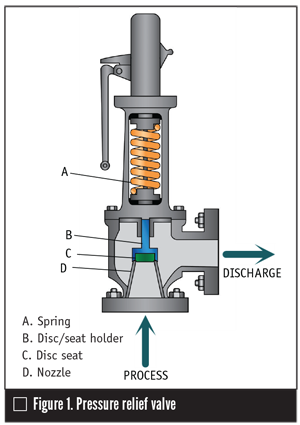
When the spring force exceeds the force resulting from the process pressure and the pressure in the discharge side (backpressure), the disc blocks the flow from the process side to the discharge. When the process pressure exceeds the valve set pressure, the disc pushes the spring, opening the valve and forcing the process fluid to the discharge pipe. The valve will remain open until the process pressure drops to about 95% below set pressure. The about-5% dead-band, also known as valve blow down, prevents the valve from chattering when the process pressure varies close to valve setpoint.
Unaccounted discharges occur when the valve chatters, which is when the vessel pressure oscillates around the PRV setpoint with an amplitude larger than the dead-band. This chattering occurs when the valve is not specified correctly, is not properly set, or the piping was not designed properly.
The valve opens proportionally to the excess pressure and returns to the closed position when the process pressure returns to normal. The discharged fluid can be released to the atmosphere or routed to a treatment unit or flare system.
In many cases, when the process pressure returns to normal, the PRV does not close completely, caused by several factors including:
- Pressure increases on the discharge side.
- The valve seat is damaged after repeated actuations.
- A deposition or formation of solids occurs between the disc and the seat.
- The process fluid is altered.
- Corrosion has occurred.
- A mechanical malfunction occurs.
PSVs
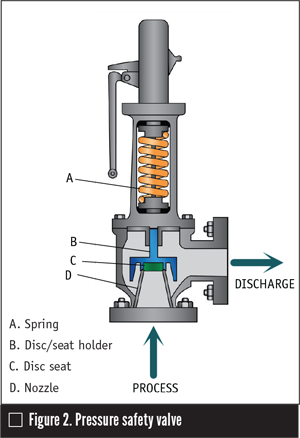
PSVs are commonly known as “pop valves” because they open completely and rapidly when the pressure exceeds the setpoint (Figure 2). The valve will remain open until the process pressure drops to about 95% of set pressure. These valves are primarily used for gas and steam.
PSVs are slightly different than PRVs. The disc blocking the nozzle has a small area and is contained in a larger diameter chamber. When pressure exceeds the setpoint, the stem starts to lift, allowing the process fluid to flow to the chamber. Because the chamber area is much larger than the one exposed by the disc, the uplifting force is much greater than the spring force and the valve opens completely.
When the discharge happens, the pressure reduces in the chamber, and the valve closes. If the process pressure is still above the setpoint, the valve keeps popping open until the pressure returns to normal levels.
When the process pressure fluctuates around the PSV setpoint value, the blocking disc will lift slightly to allow the chamber to fill. The process fluid vents to the discharge pipe, reducing the pressure but not opening the valve completely. This process is called simmering, and it can cause material buildup on the disc seating and stem misalignment, which prevents the valve from closing completely. The discharge caused by simmering and its side effects are not usually detectable by conventional methods.
PSVs are commonly equipped with a lever so an operator can initiate a manual release. This release is useful for testing the valve, cleaning scale or solids deposited on the seat surface and dealing with special process conditions during startups or shutdowns.
RDs
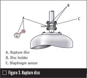
Unlike pressure relief or safety valves, the rupture disc will remain open until the ruptured diaphragm is replaced. Diaphragms are less susceptible to causing fugitive emissions, but a possibility exists of pitting corrosion, which creates pinholes leading to undetectable leakage.
RELIEF VALVE (RV) WITH RD
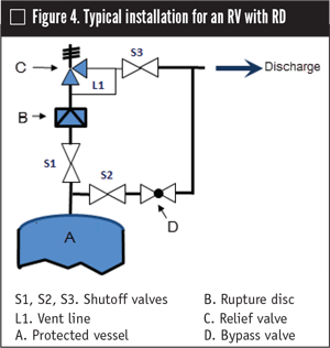
In some applications, a rupture disc is installed upstream from the RV (Figure 4).
The main reasons for this are:
- The RD can prevent fugitive emissions through the RV.
- The RD protects the RV against corrosive process fluids. The RV may not be available with the material required for long-term resistance to the process fluids, or it may be too expensive. The RD diaphragm works as a shield between the process and the RV.
- The RD protects the RV against solid particles. These particles can damage or prevent the RV from working properly, failing to open, or remaining open after a release.
- The RD protects the RV against frozen vapors, material polymerization, hydrate formation or other problems that may prevent it from working properly.
To avoid this problem, a vent line is often installed to keep the pressure between the disc and the valve equal to the discharge line pressure (Figure 4).
Bypasses and discharges through PRDs are considered a violation of laws in many countries, requiring plants to monitor discharges of individual PRDs.
EFFECTIVE MONITORING OF PRDS
A typical plant will have several different PRD makes, models, sizes and operating pressures from various vendors. This makes it difficult to design a standardized monitoring system.
Monitoring how many times PRDs activate and how long each releases product helps plant personnel understand processes better. It also can improve combustion control. However, monitoring does not give visibility on leakages caused by PRD malfunction.
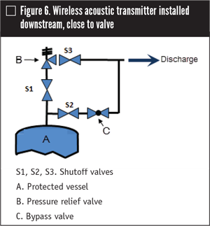
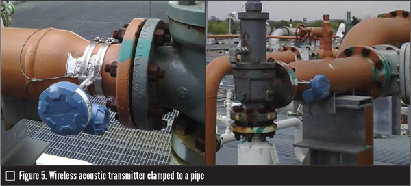
A reliable, effective and economic way to monitor PRDs is to use wireless acoustic transmitters.
PRD operating conditions can be determined by:
- An increase in noise level indicates that the PRD has been activated.
- When the noise level returns to the previous level, it indicates that the PRD is no longer discharging.
- When the noise level returns to a level above the previous level, it indicates leakage from the valve not closing completely. This may be caused by deposition of particles or scale between the disc and its seat or from a mechanical misalignment.
- When the noise level changes continuously, it indicates that the valve may be simmering or chattering.
- Temperature changes can be an additional indication that validates a release.
RV Monitoring
RD Monitoring
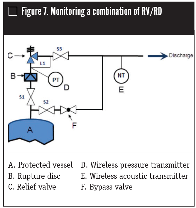
Some types of RDs are equipped with a burst detector that generates a discrete signal indicating disc rupture. Devices also can be installed on the RD surface that can detect when the disc ruptures and indicate the event through a discrete signal. RDs also can be monitored with the use of a wireless acoustic transmitter that can detect when the disc ruptured and the duration of the discharge, as happens with RVs; but with RDs, the devices also may detect small leaks caused by pinholes.
MONITORING RV/RD COMBINATIONS
Once RDs burst, they cannot close again, so the process fluid will be discharged until not enough pressure exists to make the fluid flow. RVs are a better solution in this case because they close when the process pressure returns to normal conditions. However, in some applications, the fluid flow must be isolated from harsh process conditions by using RDs. In normal operation, the RV is not in contact with corrosion, gumming or hot process fluids. If the vessel pressure reaches unsafe levels, the RD bursts, followed by the RV opening. The RV closes when the pressure returns to safe values.
The wireless devices mentioned in this article use wireless HART technology, which is an open standard that provides secure, reliable and flexible wireless communication. Planning, installation and configuration of the wireless network is simple and flexible.
By monitoring pressure relief devices in this way and feeding the results into a valve asset management database, it is possible to recognize potential failures before they happen and identify actions that could eliminate or reduce the chance of the potential failure occurring.
MARCIO DONNANGELO is a global business development manager with Emerson Automation Solutions (www.emerson.com). Reach him at marcio.donnangelo@emerson.com.
RELATED CONTENT
-
Direct-Sealing Diaphragm Valves Offer Novel Approach
As modern industries such as hydrogen electrolysis and biotech make dramatic technical advances, engineers and researchers must sometimes turn to nontraditional process control systems.
-
CASE STUDY: Predictive Maintenance with Retrofitted Electraulic Actuation
Electraulic Actuation is a brand of electro-hydraulic actuation unique to REXA. It combines the simplicity of electric operation, the power of hydraulics, the reliability of solid state electronics, and the flexibility of user-configured control.
-
The Dos and Don’ts of Isolating Pressure Relief Valves
Typically, isolation valves are used to block off a pressure safety valve (PSV) from system pressure, so that maintenance on the valve or related equipment can be conducted without a shut down.




 Unloading large gate valve.jpg;maxWidth=214)