New Requirements for Actuator Sizing
After decades of confusion, the American Water Works Association has created new standards for actuator sizing that clear up some of the confusion and also provide guidance on where safety factors need to be applied.
#water-wastewater #VMAnews #standards
After decades of confusion, the American Water Works Association (AWWA) has created new standards for actuator sizing that clear up some of the confusion and also provide guidance on where safety factors need to be applied.
BACKGROUND
AWWA published the first standard for quarter-turn valves in 1954: AWWA C504, Rubber Seated Butterfly Valves. In later editions, a prescribed methodology was developed for manufacturers to develop coefficients and calculate the torques required to operate valves under normal operating conditions. Several components of valve torque and their associated coefficients were defined including seating torque, bearing friction torque, hydrostatic torque, dynamic torque, etc. All of them varied greatly according to valve size, operating pressures and flow rate.
To complicate matters, experience showed that how the valve is installed and upstream flow conditions can have a significant influence on the valve torque as well. For example, if a butterfly valve is installed immediately downstream of an elbow pipe or a pump, the asymmetric velocity in the pipe can cause a significantly higher dynamic torque.
VALVE TORQUE
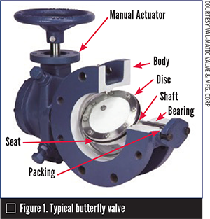
To gain an understanding of quarter-turn valve torque, let’s walk through an opening stroke of a butterfly valve such as the one shown in Figure 1. A butterfly valve consists of a body bolted to the piping system. A disc is supported by a shaft that rotates within radial bearings secured in the body. The valve has a seating system consisting of a resilient seat and a stainless-steel mating surface to provide zero leakage at full pressure.
In the closed position, the disc will typically see a high differential pressure, which creates forces on the disc that are transferred to the bearings. To open the butterfly valve, actuator torque is applied to the valve shaft equal to the friction forces around the resilient seat, packing and bearing surfaces. During mid travel (as seen in Figure 1), the friction forces on the bearings drop but the fluid flow induces a dynamic torque from unbalanced aerodynamic forces across the disc.
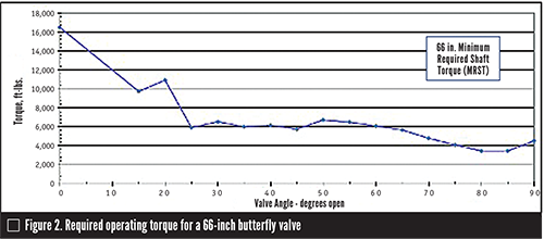
Using test-based flow and torque coefficients, manufacturers calculate and plot torques as shown in Figure 2. High torque at the 0 degrees or closed position exists because of seating, bearing and packing torque. As the valve travels from 0 degrees closed to 90 degrees open, the dynamic and bearing torques vary as shown. These data points represent the minimum required shaft torque (MRST) at each travel location.
MANUAL ACTUATOR SIZING
Sizing a manual handwheel or nut--operated actuator is a two-part process. First, the actuator must have a rating greater than the MRST at all positions of travel. Then, with consideration given for the efficiency and mechanical advantage of the actuator at each position, the required input torque for the actuator is computed so that the handwheel rim pull will be less than 80 pounds and the nut torque is less than 150 foot-pounds or similar criteria. In some cases, a larger handwheel or a spur gear may be required.
CYLINDER ACTUATOR SIZING
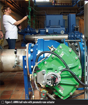
Cylinder or vane actuators provide remote operation of valves using hydraulic or pneumatic power (Figure 3). In general, cylinder actuator sizing is based on the mechanical advantage, efficiency and minimum supply pressure. A safety or application factor (AF) is needed to allow for supply pressure loss through controls and cylinder piping. The construction and operation of cylinder actuators and controls are described in detail in AWWA M66. Further, many cylinder actuators are equipped with springs to make the valve fail open or closed so the spring force must be added to the MRST. When controlling the position of the valve with a pneumatic power source, a higher AF is needed to maintain stability because of the compressibility of the pneumatic fluid.
MOTOR ACTUATOR SIZING
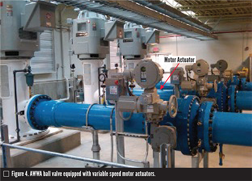
The gear portion of a motor actuator is required to have a rating greater than the MRST. The combined gear and motor actuator is sized based on its mechanical advantage, efficiency, minimum supply voltage and required speed of operation. Motor actuators are equipped with limit and torque switches to protect the gear portion and the valve from excessive motor torque. An AF is needed to assure safe operation of the motor actuator as field conditions vary or valve component degradation occurs over time. Also, in modulating service, the necessary frequent starts and stops require greater safety in sizing the motor. The electric motor must also produce 1.5 times the MRST without stalling.
ACTUATOR SIZING TORQUE
According to AWWA C504, the actuator sizing torque (AST) should be calculated by the actuator manufacturer and based on the MRST times the AF. These requirements have been added to the 2015 versions of the AWWA butterfly and ball valve standards. AWWA standards committees are working on adding them to the applicable power actuator standards to provide consistent direction across the industry.
JOHN V. BALLUN, P.E. is the president and CEO of Val-Matic Valve & Mfg. Corp. (www.valmatic.com) and a regular contributor to VALVE Magazine. Reach him at jvb@valmatic.com.
REFERENCES
- American Water Works Association (AWWA), 2015, ANSI/AWWA C504-15: Standard for Rubber-Seated Butterfly Valves. Denver, CO: AWWA.
- American Water Works Association (AWWA), 2015, M66: Cylinder and Vane Actuators and Controls - Design and Installation. Denver, CO: AWWA.
- American Water Works Association (AWWA), 2017, M49: Quarter Turn Valves: Head Loss, torque, and Cavitation Analysis. 3rd ed. Denver, CO: AWWA.
RELATED CONTENT
-
Are Bypasses Needed With Today’s Waterworks Gate Valves? New Information Says They’re Not
Gate valves are the most common valve used in the water utility industry.
-
A Reference Manual on Elastomers
The history and general application of elastomers in pipes, valves and fittings is the subject of the Manual of Practice developed by the American Water Works Association (AWWA).
-
The Eccentric Plug Valve
The first non-lubricated eccentric plug valve was developed in the late 1920s, designed to solve the issue of pitch buildup in paper mill valves.


 Unloading large gate valve.jpg;maxWidth=214)