Power Plant Isolation Valves Beat the Heat
About a century ago, pressures of 300 psi and temperatures of 400°F (204°C) were normal for steam power plants.
#iiot
The SC range is defined today as pressures between 3,553 psi and 4,133 psi and corresponding temperatures between 1004°F (540°C) and 1076°F (580°C). The reason these pressures and temperatures are so important is that supercritical water has a lower density and a higher motility (the molecules move more freely), which enable more efficient transfer.
These SC ranges are common in today’s power generation, and plants are now climbing to higher levels of pressure and temperature in a quest for even higher efficiency. A new pinnacle called ultra-supercritical (USC) is becoming more common. The difference in performance (heat output) between a SC and a USC plant is about 5-8%, which seems like a low number. But in the power industry, those percentages are significant.
Currently, there is only one commercially operating USC plant in the United States—The John W. Turk, Jr. Power Plant in Fulton, AK. Turk came online in 2012 and so far, it has been a great success.
What all this means to valve manufacturers and plant owners is they are now dealing with old designs and materials that will not perform as required in these new power plant environments. The biggest challenge will be the need for acceptable high temperature materials of construction.
PEAK PLANT PROBLEMS
Beyond the challenges of temperatures and pressures lies an additional obstacle in the way of increased operating efficiencies—peaking power plant operation. In years past, almost all power plants were always in operation (we refer to them today as “base load” plants). In other worlds, base load plants were like the main electrical service to homes—always “on.” In contrast, a peaking plant only runs when needed (like a switched-on light in a room), usually at peak times of the day or peak months of the year. As long as a plant is operating at constant temperatures and pressures, the potentially damaging effects of radical temperature and pressure changes on components are not an issue. In a peaking plant, however, temperatures may oscillate by 500°F (260°C) every day. This periodic temperature variance, on top of up and down pressure levels, is very hard on the equipment, including the valves, which are expected to last 30 years or more.
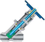
To meet the isolation valve requirements in these plants, legacy valve types as well as newer designs are employed. Gate valves are still popular, but Y-pattern globes have taken a share of the business. The metal-seated ball valve has also taken some of the market. Even high-performance, metal-seated butterfly valves are being tried for certain applications.
For gate, globe and check valves to meet SC and USC requirements, pressure-seal bonnets should be demanded. Bolted bonnet in Class 2500 above designs are cost-prohibitive, and creep of the bonnet bolting can pose problems.
GATE VALVES
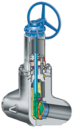
Gate valves in high-pressure steam service are still popular. Their biggest advantage here is the very low pressure drop through the open valve, a pressure drop almost equal to straight pipe. Gate valves do present a few drawbacks in that they generally have more operability problems, a higher leakage rate than globe valves, a tendency to trap fluid in the bonnet, and they are more difficult to repair in-sutu.
Various gate valve wedge designs are used in high-pressure steam service, and each has pros and cons. The solid wedge is the only viable type for small diameter (less than an inch-and-a-half) valves. Larger, solid disc valves can jam in the body as a result of temperature changes during heat-up and cool-down.
Split Wedge
Split wedge designs (where the wedge is comprised of two separate pieces) tolerate line loads and temperature transients more easily by allowing each wedge piece to align with its matching seat. This feature is used in larger gate valves to overcome thermal binding problems. Because of the increased seating integrity of this design, both wedge pieces can simultaneously seat, which can result in locking potentially damaging fluid pressure into the body cavity. The split wedge design is also easier to repair than solid-wedge or many flex-wedge designs.
Flexible Wedge
Flexible wedge designs offer many of the same features as split wedge designs. Their flexibility allows expansion and contraction of the wedge and prevention of temperature locking into the valve body. The flexible wedge designs are easier to repair than solid wedge designs. A disadvantage of the flexible seating, however, is that inadvertent upstream and downstream seating can result in fluid pressure locked in the body cavity.
Parallel-Expanding Wedge
Parallel-expanding wedge designs are more complex in design, but offer several advantages over wedge-type designs. For one thing, when opening and closing the wedge, faces do not contact the seating surfaces. Only when the valve is closed do the wedge assemblies slide away from each other and form a seal on both the upstream and downstream body seats. This means prevention of unwanted contact between sealing surfaces as the valve opens and closes. Because of the seat design’s potential to cause bi-directional sealing, internal body cavity fluid pressure can be locked in the valve.
The parallel slide double-disc gate, also called a parallel expanding double-disc gate, is constructed in two pieces with each piece floating independently and mating to its requisite body seat (Figure 1). The wedge sections are pre-loaded using springs. This design provides much better immunity from thermal locking. Parallel slide double-disc designs can only provide unidirectional sealing, however. They are also most effective in larger sizes and in applications where there is adequate differential pressure across the sealing surfaces.
GATE VALVE PORT SIZING
In subcritical power plant applications, as well as in most petrochemical and refining installations, valves are sized at B16.34. These designated dimensions are generalizations and do not take velocity of flow, pressure drop or noise into consideration. In the case of SC and USC applications, valve port (seat sizing) is critical. With pressures of over 3,500 psi, fluid velocity and related pressure drop through the valve can be damaging and dangerous.
A side effect of high velocity is noise, which requires abatement when the plant is located near the general public. In the United States, no federal noise abatement requirements have been made for power plants. However, the European Union (EU) has stringent requirements, which are listed in the EU Environmental Health and Safety Guidelines. Those guidelines allow no more than 60 weighted decibels (dba) during the day and 45 dba at night, which are measured half a kilometer (a third of a mile) from the sound source.
Part of the issue in port size is glossed over by using the term “full port,” a term that in piping parlance can be ambiguous at best and useless at worst. Considering the fact some newer piping materials are much stronger (which means higher allowable stresses), but also have thinner walls and larger inner diameters (IDs), the relationship between full-port B16.34 dimensions and the actual matching pipe ID may be very different.
From a valve performance standpoint, this can mean larger port (seat opening) sizes so they can handle higher velocities, lower pressure drops and lower decibel levels. However, overkill is not good. Larger-than-required valve ports mean larger actuators with a resulting higher cost. Oversized ports also can lead to flow issues that adversely affect nearby check valves.
India’s National Thermal Power Corporation does not recommend valve port sizes to valve vendors, but it does specify maximum allowable velocities and maximum pressure drops. This is an idea that U.S. power plant design engineers may need to consider.
BODY CAVITY PRESSURE RELIEF
All of the gate valve designs that suffer from unwanted body cavity pressure buildup can be modified to alleviate the potential problem of body cavity pressure. Modifications include:
1) Adding external bypasses to vent the pressure either upstream or downstream, 2) Drilling a hole in the upstream side of the disc, 3) Adding a pressure relief valve to the body, and 4) Incorporating an internal bypass design.
GLOBE & BALL VALVES
Even though the Y-pattern globe valve has a better flow rate than the standard T-pattern globe, it is no match for the gate valve in terms of pressure drop, cavitation prevention and velocity through the valve.
The use of ball valves in power plant isolation service is limited to metal-seated designs. Because these are non-trunion types, the full force of the flow is directed onto the ball when in the closed position. This means these valves are limited to smaller sizes and often have reduced ports to lower the required closure torque. The reduced port design creates a change in the Cv of the valve because of pressure loss and a higher exit velocity. For vents and drains seldom operated, this is not a problem; but for continuous process applications, service issues could arise.
MATERIAL SELECTION AND CREEP
To understand what creep is, we need to look at the property of yield strength in steels. If a load that is slightly less than the elastic limit is applied at room temperature, the steel elongates, and when the load is removed, it will return to its original length or shape. This elastic behavior will continue regardless of the number of loadings made on the component. If, however, an identical piece of steel is heated to slightly elevated temperatures and a load is applied, after a length of time, the specimen may assume a permanent deformation even though the applied load is below the elastic limit at room temperature. This phenomena is called creep, and it can result in catastrophic failures of metallic components.
Consider body-bonnet bolting as an example. Creep can mean the bolts relax and lose their load, which means the body/bonnet could leak. To test the tendency of a metal to creep under given conditions, a specimen is held under constant temperature and subjected to a constant tensile load for a suitable length of time. The load causes the specimen to elongate gradually. This elongation is then measured over a period of hours, days, weeks, months or years. From these tests, the creep behavior of a particular metal can be determined.
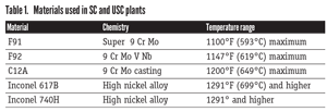
Some of the newer materials used in SC and USC power plant valves are shown in Table 1.
DESIGN STANDARDS ARE KEY
The working pressures at various temperatures of most metals used in valve pressure boundary construction are listed in the American Society of Mechanical Engineers (ASME) document B16.34, Valves‒Flanged, Threaded and Welding End. The tables in B16.34 also take into account the creep resistance of particular steels. To meet the requirements for USC power plants, new materials have been added to the B16.34 document, while other B16.34 code-case listed metals are also being considered. Austenitic stainless steels such as 304ss and 347ss can meet very high temperature requirements (especially in the high carbon “H” grades), and the section thickness would be much greater because of the lower strength of these materials.
The problem with relying solely on B16.34, the traditional standard for power plant valve design, is the basis of the calculations as well as some of the listed specifications, such as wall thickness. Looking at the history of the document provides insight into why that is. Shortly after World War II, data was gathered on valve design, and wall thickness calculations were developed. Much of this research was done in the Crane R&D facilities in Chicago.
The initial result of that research led to the creation of the Manufacturers Standardization Society (MSS) SP-66, Pressure-Temperature Ratings for Butt-Welding End Valves, in 1964. The aim of the B16.34 document, which was first published in 1974, was standardization of sizes and basic dimensions to increase manufacturing production while maintaining a conservative safety margin. This was a boon to manufacturers because it allowed common dies and patterns to be used for valves of different materials. The area of wall thickness, with its one-size fits every-material approach, is an example. However, that example unfortunately does not fit well into today’s power plant design process.
As a result of the poor fit of the B16.34 document for SC and USC power plant valves, designers have looked to different valve design standards. The most important of these is the European standard EN 12516-2, Shell Design Strength. This document has become the first reference for SC and USC valve designs using the newer, high-strength/high-temperature materials because of its calculation methods and formulas (which are different from B16.34).
AN EXPERT OPINION
One of most prominent leaders in SC and USC valve design, Rana Bose, president of Rana Bose & Associates, feels strongly that this newer type of design requires an integrated approach.
“Valve specifications must take into account the heart of valve design concepts such as seat bore and its interactivity with high velocity, pressure drop and noise control requirements,” Bose reports. “Newer valve materials necessitate a fresh look at design concepts that are more responsive to thermal cycling operations, peaking plants and thermal distribution in sealing areas,” he adds.
PROPER WELDING
No matter which alloys are chosen for valve components, coincident welding and post-weld heat treatment (PWHT) issues must be overcome because all of the valves will be welding-end or socket-weld designs. Welding engineers disagree on the correct procedure for PWHT on C12A material, as well as how best to handle some of the more complicated, newer materials. In some cases, pipe also may be a different material than the buttweld end valve. This requires the use of suitable dissimilar welding filler materials and welding procedures and may mean possible complications with in situ, PWHT procedures.
Another problem that can arise in SC and USC valve applications is the oxidation of graphite-based packings at very high plant operating temperatures. Graphite packings are said to oxidize at 1200°F (649°C). This may require newer packing designs or fins around the packing area to dissipate the heat.
GETTING THERE FROM HERE
In the U.S., nuclear has become a no-no and traditional coal-fired plants are viewed as evil. At the same time, the nation’s power consumption will only rise. To achieve higher power generation efficiencies and reduce emissions of environmentally damaging gases, new technologies must be embraced.
In many other areas of the world, including India and China, SC and USC plants are already very popular. Since our country resides on the same planet as all the rest of the world, it’s to our advantage to retire even more of our inefficient coal-powered plants and replace them with much more efficient USC facilities. The Department of Energy has invested in pilot plants in the United States, but we are still behind other countries in employing this technology. Part of the reason is slowness in solving some of the challenging materials issues. Another issue is the anchor that the government attaches to any new power plant project. For example, it currently takes six to seven years to license a new natural gas power plant.
One factor is certain, however: North American valve manufacturing companies will be at the forefront of matching safe, functional valve designs with the needs of emerging power plant technologies.
A special thank you goes to Rana Bose, who provided not only comments, but valuable research information for this article.
GREG JOHNSON is president of United Valve (www.unitedvalve.com) in Houston. He is a contributing editor to VALVE Magazine, a past chairman of the Valve Repair Council and a current VRC board member. He also serves as chairman of VMA’s Education & Training Committee, is vice chairman of VMA’s Communications Committee and is past president of the Manufacturers Standardization Society. Reach him at greg1950@unitedvalve.com.
RELATED CONTENT
-
Pneumatic Valves: New Technology for a Digital Transformation
Principles built around the Industrial Internet of Things have guided the automation industry’s rapid adoption and mainstreaming of many production systems.
-
Curtiss-Wright Completes Acquisition of WSC Inc.
WSC is a provider of state-of-the-art simulation technology that supports the design, commissioning and reliable operation of commercial nuclear power generation and process plants worldwide
-
CASE STUDY: Building the World’s Most Secure Data Center Inside a Mountain
Securing data is vital to a world that has come to depend on it. All options are on the table as long as they deliver added protection.


 Unloading large gate valve.jpg;maxWidth=214)