Regulators versus Control Valves: What’s the Best Fit?
The combination of North American shale fields that continue to fuel high levels of new domestic oil and gas projects and ongoing global efforts means the need for efficiency in instrumentation selection has never been higher.
#controls #automation
THE DIFFERENCES
Regulators and control valves are different in function and the way they operate in a few ways.
The design of a typical control loop allows control valves to manipulate a range of process variables depending on which variable is measured for control. Examples of this include valves with capabilities for control of flow, level, temperature and pressure. The process control variable is measured by a sensor/transmitter and then communicated to a host control system, which is typically a distributed control system (DCS). The DCS interprets how the valve should respond to a deviation from the predetermined setpoint value, then communicates a signal back to the DCS controller reporting the extent to which it needs to open or close to return to the predetermined setpoint. The DCS controller receives that signal and then sends a signal to the valve’s positioner, which then converts the electronic signal to a pneumatic signal, thereby physically making the change in the valve’s throttling position.
The main operational difference between a control valve and a regulator is that, contrary to the control loop design mentioned above, regulators are process-powered valves without the need for an external power or instrument air source to operate. A regulator typically applies the pressure of the controlled process fluid against a diaphragm. This diaphragm then opposes a compressed spring to achieve force balance with the diaphragm at a given set pressure. Any change in the controlled pressure causes the diaphragm to move, which causes the flow area of the regulator to change, allowing more or less process fluid through the regulator. A simple example of a pressure-reducing, direct-operated regulator design compared to a control valve in a control loop is shown in Figure 1.
Because of the use of process fluid pressure as a means for control, regulators are functional as pressure control valves.
As a process-powered device, the controlled pressure must change to modify the flow rate through the regulator. An example is a pressure-reducing regulator that controls fuel gas pressure for a compressor engine. If the rate of fuel gas consumption for the compressor engine increases, gas pressure in the line between the regulator and compressor engine will decrease. This reduced pressure, acting on the diaphragm, will cause spring force to overcome the force generated by the diaphragm. The diaphragm is connected to the regulator’s valve plug, and when spring force moves that diaphragm, the regulator’s valve plug opens further, allowing additional fuel gas through an expanded flow area. As long as this increased consumption rate is maintained, the regulator will hold downstream pressure constant at a value slightly below the set pressure. This concept is referred to as droop or offset. It is the allowable deviation from set pressure to meet downstream consumption.
Another difference is related to the design pressure rating of the regulator’s body. While a control valve can handle the same pressures on the inlet side as the outlet side of a valve, a regulator may have a lower pressure rating on the control pressure side of the regulator. This is because the process fluid pressure is applied directly to the internal components of the diaphragm casing. It would be similar to applying process pressure directly to the actuator portion of a control valve assembly instead of the controlled instrument air supply pressure. While a few exceptions to this rule exist among high-pressure, pilot-operated regulators, both the inlet and outlet side design pressures need to be considered in selecting a regulator.
On the other hand, control valves are available in much larger sizes and higher pressure classes than regulators. They can handle any process fluid by selecting compatible metallic trim materials. Regulators, in almost every case, will have at least one elastomeric material in contact with the process fluid, which means limited use in some highly corrosive applications.
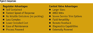
Figure 2 depicts typical advantages of regulators and control valves.
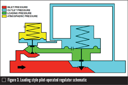
To reduce droop and maximize accuracy, a pilot-operated regulator can be used. These regulators require only 1–3% droop or deviance from setpoint to achieve full capacity. Direct-
operated regulators need 10–20% droop. Pilot-operated types achieve this accuracy by adding a small, direct-operated regulator (the “pilot”) to the main regulator, which introduces gain to the system and increases sensitivity to changes in the controlled pressure. Pilot-operated regulators have much larger orifices as well, which allows higher capacities as well as heightened accuracy compared to self-operated regulators.
CRITERIA OTHER THAN USE
When choosing between a regulator and a control valve, design considerations outside of the process data itself need to be considered.
For example, if diagnostic monitoring or predictive maintenance feedback are required, only a control valve that can communicate diagnostic data to a control system should be considered. On the other hand, if the valve’s operation is critical to the facility, a regulator would be the more appropriate choice because auxiliary power is not required to maintain its functionality.
While maintenance and total installed costs are typically lower for regulators, project specifications or site standards may require a control valve. Also, certain applications mean technical advantages for either a control valve or a regulator and other applications create conditions where one or the other should be avoided altogether. Here are five example applications:
BLANKET GAS CONTROL
Blanket gas control, or tank blanketing, is the process of maintaining the pressure of a mass of inert gas, typically nitrogen, at the top of a tank or vessel, thereby preventing exposure to, or release of, a liquid product to the atmosphere. For a utility header line, for example, nitrogen, which is typically 50 psig to 200 psig, is reduced to a pressure of just inches of water column. This is done to maintain the gas blanket for when liquid product is pumped out of the tank or when environmental temperature changes cause a pressure change inside the tank. Similarly, a pressure control device might be used to relieve gas from the tank or vessel in the event pressure rises when loading liquid product.
Regulators most commonly are used for both the pressure-reducing valve and back pressure regulator (which would be a non-ASME relief valve). This is because the regulators can monitor the tank pressure directly and respond more quickly to changes in blanket gas pressure, preventing overpressure or underpressure from occurring on the tank.
There may be instances for which the tank design pressure is higher than the design pressure of the regulator on the side maintaining low-pressure control. The regulator design for tank blanketing applications typically includes large diaphragms that are very sensitive to changes in low pressures and can be damaged by pressures well above the setpoint. In these cases, setting a safety relief valve to a pressure below the design pressure of the regulator is important. If this action is not possible, it may be necessary to use a control valve even for tank blanketing applications.
PLANT FEED GAS SUPPLY
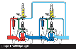
Figure 4 is an example of a wide open monitor, where the pressure between the two regulators is not controlled. A working monitor arrangement would add a second pilot to the monitor, which would control the intermediate pressure between the two regulators. This would provide a means to prove the monitor regulator is operational and capable of throttling pressure if the worker ever failed to open.
SEVERE SERVICE
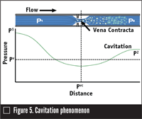
The term severe service is typically applied to valve applications where excessive noise, cavitation or flashing occur from excessive pressure drop across the valve. For gas applications that predict high noise levels, instead of adding insulation or another path treatment noise-masking method, source treatment can be applied to attenuate the noise within the valve itself. A small number of regulators have trim types capable of noise attenuation, but attenuating control valve trims are more widely available. These can be customized to shift the sound frequency out of both the audible and the vibration-inducing range, thus avoiding damage to the valve, piping and downstream equipment.
DIFFERENTIAL PRESSURE CONTROL
Differential pressure control applications in oil and gas production are designed to maintain production pressure from the wellhead outlet at a point above the pressure of the pipeline into which the fluid will be loaded for transmission. Differential pressure control is needed because wellhead pressure is constantly varying, and a positive differential pressure from the pipeline must be maintained without overpressuring the line. These wells are typically in remote areas without access to instrument air or other actuator power supplies, which eliminates control valves from consideration. Regulators are capable of maintaining differential pressure between a reference point such as the pipeline pressure, and outlet pressure from the regulator. Direct-operated regulators are commonly used in these applications because they provide the fastest speed of response to pressure fluctuations or changes.
HEATER OR BOILER FUEL GAS CONTROL
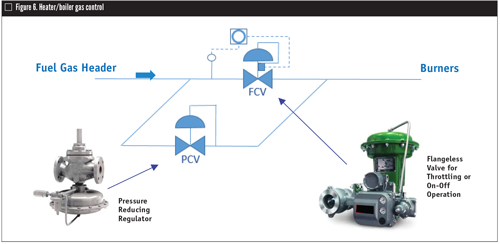
Boiler and heater fuel gas control is an application that commonly uses a control valve and regulator in tandem. This application takes fuel gas from a header line in the 100-psig to 150-psig range and reduces pressure to less than 1 psig while keeping up with fuel demand for the boiler or the heaters. During normal operation, a large volume of fuel gas is required, which typically results in using a high-capacity ball valve for control. In this system, a very-low-flow condition occurs when the heaters/burners are not fired, but the boiler or heater pilot lines must be maintained. A pilot-operated regulator is typically installed parallel to the control valve for very accurate low flow and pressure control (Figure 6).
CONCLUSION
Pressure control valve selection will always be a critical aspect of facility design and maintenance. By understanding the capabilities and functionalities of both control valves and regulators, engineers tasked with selecting control valves or regulators can start with an optimal solution in mind or reduce rework for their pressure control applications.
Keith Erskine is regulator business manager at Puffer-Sweiven, Emerson’s local business partner in South Texas and Latin America. Most of his career has been focused on control valve and regulator applications at engineering contractors with a diverse scope of upstream oil and gas, refining and chemicals projects. Reach him at Keith.Erskine@puffer.com.
Vincent E. Mezzano is a Fluor Fellow and Fluor’s subject matter expert in control valves, on/off valves, actuators and relief valves. Mezzano is chairman of ISA SP96 Valve Actuator Committee, ISA SP 75.05 Control Valve Terminology and ISA SP 75.24 Control Valve Actuator Sizing and Selection, a member of ISA Standards and Practices Board, and a voting member of ISA SP 75 Control Valves. He is also an active member of the PIP Process Control Team. Reach him at vince.mezzano@fluor.com.
This article is based in part on a presentation on differentiation of capabilities and proper applications of control valves versus regulators delivered at the 2014 Emerson Global Users Exchange.
RELATED CONTENT
-
Proper Care of Knife Gate and Slurry Valves
How to resolve—and avoid—field failures of knife gate and slurry valves
-
Back to Basics: Globe Valves
There are many applications where the globe valve outshines other designs, so the future is still bright for these long-time favorites of the flow control industry.
-
The Dos and Don’ts of Isolating Pressure Relief Valves
Typically, isolation valves are used to block off a pressure safety valve (PSV) from system pressure, so that maintenance on the valve or related equipment can be conducted without a shut down.





 Unloading large gate valve.jpg;maxWidth=214)