Rigging and Lifting of Large Valves
This article outlines the challenges of lifting large valve assemblies weighing several tons and illustrates the industrial rigging equipment and lifting operations typically used for these valves.
#automation #maintenance-repair
VALVE CHARACTERISTICS
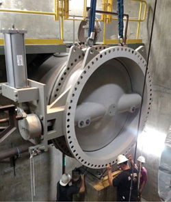
Rigging is defined as connecting a load to a source of power so that it can be lifted and moved safely and predictably. To rig a large valve, a basic understanding of valve construction is required. Figure 1 is typical of most large valves consisting of a body, a closure member that either rotates or translates in the body, and an external actuator, which is used to operate the closure member.
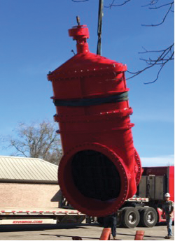
The body may include a flange or flanges with bolt holes that can facilitate lifting. If the valve is installed with the actuator removed, the closure member must be secured from rotating or translating, which will shift the load. The interior of the valve is not to be used for lifting. Valves also should not be lifted using straps, cables or chains through the valve interior because the precision-machined seating surface could be damaged (per American Water Works Association—AWWA—guidance). When moving a valve with a forklift, it is important to protect the valve flanges from scrapes or gouges. The flange surfaces are machined to accept and seal to mating pipe gaskets and should not be treated like structural beams. It is recommended that large flanged butterfly valves with eyebolts or rods through the flange holes and large gate valves be lifted with straps around the valve body.
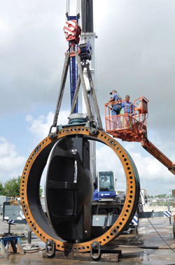
It is also important to note that the center of gravity of the valve varies with the location of the closure member and the relative weight of the actuator. While it’s logical to rig to the centerline of the valve, doing so may place the load out of balance. The center of gravity must be estimated, and the slings or cables connected in such a way that they balance the load. In Figure 2, the lifting slings are placed toward the actuator on this 36-inch pipeline valve to balance the load.
VALVE RIGGING EQUIPMENT
Many types of rigging equipment are commonly used with valves. It is dangerous to simply insert the crane hook into the nearest flange hole or cavity of a valve. Valves can be made of grey iron, which can be brittle and may not support the high, localized stresses from a crane hook.
The connection to the crane hook is typically made with a combination of shackles, synthetic slings, wire rope slings and chain slings. It is recommended that a swivel eye bolt or hoist ring be employed to connect to a valve flange as shown in Figure 5. These devices are simply inserted into two or more flange holes and automatically aligned to the lifting strap angle to prevent damage to the strap or the eye bolt. Alternatively, bars of diameter equal to the bolt holes can be inserted into opposite flange holes for lifting.
Large valves are easily flipped over with swivel rings. A large butterfly valve can be lifted and stood up on its edge. Then, the swivel rings can be inserted into one side of the valve’s flange face and re-lifted. The valve will swing from the vertical and can be lowered down flat to the ground on the other side. Needless to say, the valve in Figure 5 would need to have the closure member rotated to be within the interior of the valve laying length if not fully closed before laying the valve on its edge. Some valve closure members extend beyond the flange face even when fully closed. Hence, it is always advisable to have wood blocking under the flange faces before setting the valve down on the ground.
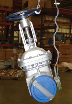
In Figure 4, we see large nylon straps used around the valve body for lifting. It is important to note that many valves have sharp edges as part of the body geometry, especially adjacent to flange faces. Slings must be padded or protected from sharp edges. Moreover, how and at what angle the strap is attached will affect its load-carrying capacity.
SAFETY
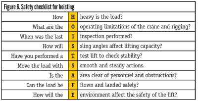
Several publications from the Occupational Safety and Health Administration (OSHA) and organizations such as the Mechanical Contractors Association of America are available for training personnel. They provide guidance for safe lifting practices and instructions on the use of rigging equipment. Figure 6 presents some of the common safety tips for lifting heavy loads.
This list is a reminder that the adequacy and condition of all equipment used should be checked. It is important to know a valve’s weight and center of gravity. Similarly, the capacity of all the lifting equipment must be confirmed. The lift zone and movement area must be clear of personnel, power lines and other equipment. But one reality is that valves are often handled outdoors in muddy trenches and horrible weather. These conditions affect the safe procedures and the strength of some equipment, such as fabric slings. Still, it’s best to work smoothly and use care at all times, no matter the conditions.
By understanding the special characteristics of valves and following safe rigging and lifting practices, the chances of successful valve installations are greatly increased.
JOHN V. BALLUN, president and CEO of Val-Matic Valve, is a regular contributor to VALVE Magazine. Ballun is also a member of VMA’s board of directors and serves on the VMA Communications Committee. Reach him at jvb@valmatic.com.
REFERENCES
1. Mechanical Contractors Association of America (MCAA), “Rigging Safety Guide,” Rockville, MD., 2010.
2. Occupational Safety & Health Administration (OSHA), ”Process Rigging” Found at: www.osha.gov/dts/maritime/sltc/ships/rigging/rigging_ships.pdf.
3. American Water Works Standard (AWWA), C516 Large-Diameter Rubber-Seated Butterfly Valves, Sizes 78 In. (2000 mm) and Larger. Denver, CO., 2014.
4. Hennepin Technical College, “Rigging Fundamentals”, 2018. www.osha.gov/dte/grant_materials/fy09/sh-19496-09/ rigging.pptx
RELATED CONTENT
-
HVOF Coatings for Severe Service Valves
Chrome carbide is one coating that can be done during manufacturing or repairs that extends service life of valves and other flow control components.
-
The Evolution of the All-Encompassing Ball Valve
The compact design, simplicity of use, ease of repair and wide performance capability have helped to make the ball valve a dominant design in modern industrial applications.
-
Isolation Valves for High-solids Severe Service
Understanding suspended solids and their effect on equipment is critical in choosing isolation valves for slurry service.




 Unloading large gate valve.jpg;maxWidth=214)

