Unique Operating Dynamics of Trunnion-Mounted Ball Valves
For a very long time, the idea has existed that a trunnion-mounted ball valve can be opened under full differential pressure if the piping system can withstand the rapid increase in pressure and the forces induced by it.
#ball-butterfly-plug #pressure-relief #automation
The operating characteristics are similar for all trunnion-mounted ball valves. For decades, field technicians commissioning new pipelines reported that actuated trunnion-mounted ball valves would open to about 20 to 25 degrees then stop before moving to a full open position. This typically happened when filling a new pipeline, and it was brushed off as something that occurred because the actuator was either undersized or the supply pressure was not set properly. As valve sizes and operating pressures have increased, the issue is manifesting itself in factories where gas tests are performed.
Manufacturers have long known about the dynamic vaning effect that occurs when opening a ball valve in situations where a high flow rate goes through the valve driven by the pressure differential. During the initial opening, the vaning forces try to close the valve again—at least until about 40 degrees of travel has occurred. When the valve is almost open, these vaning forces reverse and try to push the ball to a full open position. For this reason, manual trunnion-mounted ball valves are fitted with worm-type, self-locking gearboxes. If a spur gear is used (which is not self-locking), the vaning forces can back-drive the ball, the gear and handwheel, which, in turn, may rip the handwheel from the operator’s grip.
FACTORY TESTING
Testing valves for operability in a factory is quite different from studying how valves will perform in the field. This is because the factory testing typically has only the expansion of the fluid trapped by the upstream seat to generate a small amount of flow when the pressure is released. The test fluid also consists of a different mass and viscosity from what might be experienced in the field. However, in high-pressure or large valves, the small amount of gas flow appears to be enough to generate an opening effect similar to what occurs in the field, which may cause some damage to the seat sealing face. This is unlikely to happen during seat hydrotests because the volume of the water displaced when opening a valve in a test stand is very small.
This finding has led to extensive research to determine any root causes associated with the operating peculiarity experienced when trunnion-mounted ball valves are opened under full differential pressure. The research was only possible by using the latest technology in pressure measurement, optical recording and computational fluid dynamics (CFD) that were run on a considerable cluster of computing cores.
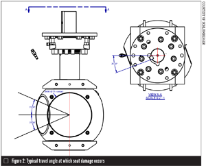
Since there is a low-flow volume during factory gas testing, a study was performed at a company facility in Voghera, Italy to learn what is happening to the pressure in various locations of the valve. Millisecond pressure recorders were installed on a test valve to measure pressure upstream, downstream, in the valve cavity and at injection ports that connect behind the seats. The results showed that at 23 degrees from open, the upstream pressure had only dropped about 47% of the starting pressure to 200 gauge pressure (barg) (Figure 1). This point was chosen because it is the angle at which slight indenting of the soft seat face material occurred (Figure 2).
The pressure in the ports behind the upstream seat followed the upstream pressure within milliseconds and highlighted the fact the seat is still pushed onto the ball with considerable force during a large portion of the opening cycle; this in turn leads to higher torque than experienced in a typical hydrotest, where water expansion is negligible or nonexistent. The rate of decay of the upstream pressure (shown as pressure drop) is driven by many factors including speed of opening the valve, pressure differential, fluid viscosity, and upstream, downstream and cavity volume.
The angle at which the slight damage of the seat face mentioned earlier occurred was translated to a time based on the fact that the actuator was a constant speed type as plotted in Figure 1. The graph shows that at 200 barg, the upstream seat is driven into the partially open ball.
Gas testing can be emulated using CFD. Test conditions are similar with natural gas as the medium, but volumes upstream and downstream of the valve are assumed to be infinite. Although this is the safer approach, limitations to testing a valve within a controlled system exist, including the fact the volume on the valve closure’s upstream side is very small.
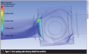
Although this scenario is extreme, it does mirror filling an empty pipeline with natural gas. Depending on the valve geometry and configuration of components, the analysis can take days or even weeks because of the memory required to run iterations. To facilitate this, the valve was positioned at selected angles of opening as opposed to every degree. Choked flow conditions existed up to 40 degrees of the opening travel with a significant pressure differential maintained upstream of the ball and behind the seat. Figure 3 shows the choke flow condition in a ball valve being opened under pressure with an infinite volume of pressure upstream.
Following multiple runs, a full-blown transient analysis from break-open to 60 degrees was run. The previous computational study was done under static conditions—the ball was analyzed at specific angles during specified times. For transient cases, the analysis examines the effects of the valve as if it were continuously opening, which provides a potentially more realistic scenario. However, the trade-off for this analysis is the amount of memory required to compute the example. Using a computational power of 200 cores, the transient analysis took six weeks to run because remeshing of the model needed to be done in minute fractions of a degree to achieve convergence of the results.
This type of analysis cannot be run for every operating condition, but it did validate the steady-state conditions previously run at various angles. The results clearly showed the seat continues to load onto the ball until the pressure is equalized between the valve cavity and upstream side of the ball. Hence, the increased torque associated with this extreme condition can be credited not only to the dynamic vaning effect, but also largely to frictional drag from the seat being loaded against the ball.
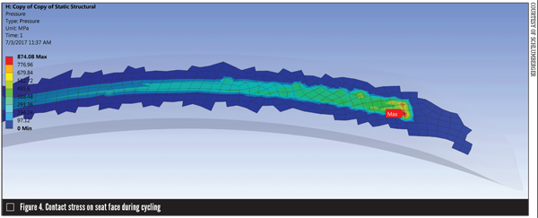
The analysis also identified the impact of the localized load on the seat face when the seat is partially supported on a half-open ball. Seat face contact load is normally studied in the closed position to evaluate sealing capability. But when the valve is partially opened, the seat is still loaded by pressure against the ball—part of the seat face is no longer supported so the section that is supported is subjected to a higher load. There also is an intensification of the contact load where the seat transitions onto the ball from its unsupported section.
The analysis work was validated by extensive gas testing where valves were subjected to an opening cycle with a high-pressure differential supplied from a large volume tank discharged to a much greater volume tank downstream. While this arrangement did not provide infinite volumes, the results mirrored the CFD analysis.
Knowing that such key factors affect valve performance, it would seem providing a design solution would be easy; however, that is not the case because so many variables must be considered.
VARIABLES AFFECTING PERFORMANCE
The first variable to be considered is the medium—liquid versus gas. While the liquid is not highly compressible, the strain energy in the pipeline upstream of the valve propels it through an opening valve in a manner similar to gas. The problem becomes more complex because the liquid may offer some lubricity, reducing the seat drag. The pipeline downstream may not be empty because such fluid acts as a buffer and equalizes pressure before the danger angles identified above are reached. The fluid viscosity, differential pressure and temperature are also factors. Multiphase flow then takes the complexity of the problem to yet another level.
Pressure differential is a huge variable in this evaluation. Many questions need to be considered, such as:
- How often will the valve be opened against full differential pressure?
- At what temperature will the stroking occur? (This affects the soft seals and the galling propensity of metal-to-metal sealing.)
- What volume downstream is being pressurized?
- What size is the valve? (The seat load in a large bore valve is substantial.)
- What is the speed of actuation?
- Are there speed controls? What happens if the speed controls are adjusted in the field? (If the valve is opened too slow, the seat face is subject to erosion. If the valve is opened too fast, the danger angle associated with high load is reached before any pressure equalization.)
- What is the type of actuation? Is it hydraulic, electric or pneumatic? (The latter imposes more dynamic loading on the valve.)
- Does the actuation fail as is, fail close or fail open? (Snapping a valve open to a flare line is an arduous operating condition for a trunnion ball valve for the reasons explained above.)
- Will the actuator accelerate/jump quickly to the danger angle once the valve is cracked open and initial pressure is somewhat released as seen in valve testing?
- Is the actuator fitted with full stroke dampening?
- Is the actuator over- or undersized?
The questions, variables and conditions are seemingly endless. A valve designed to meet every perceived operating condition would be extremely overdesigned for what is generally required. Also, every operating condition cannot be analyzed to determine performance boundaries.
It is essential to understand that these traits are common in all trunnion-mounted ball valves irrespective of design or manufacturer. The effects can be reduced somewhat by design, but cannot be removed if the valve has pressure-energized seats. It is also important to recognize that opening valves under full differential pressure with little or no pressure downstream also impacts other valve types (such as gate and butterfly valves) in a different manner.
WHAT CAN BE DONE?
- End users and contractors designing systems in which large valves are used or large volumes will be filled, or where high pressures are present should consider adopting a bypass system whereby a small valve is used to prefill fluids prior to operating the main valves.
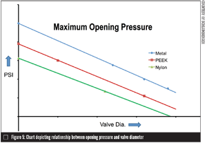
- Manufacturers should establish charts showing the valve bore size, seat material and pressures to which the valve can be opened without potential damage of the seat sealing surface (Figure 5).
- Operating speeds need to be more closely controlled or scrutinized. The industry-accepted value of 1 second per inch (s/in) of bore is allowed for closing (faster speeds for closing can be readily achieved depending on the design); however, opening time should be around 3 s/in of bore.
- Large pneumatic actuators should have full stroke dampening to inhibit the actuator from jumping to the dangerous angle associated with the high-seat load following the initial release of pressure. If the pneumatic actuator is not dampened, the recommended opening pressure should be reduced by at least 15%.
CONCLUSION
Testing trunnion-mounted ball valves opening under full differential pressure shows that, by knowing what that pressure is for a given diameter, the valve’s life can be increased and the design of piping systems improved.
RONALD MANSON is an engineering fellow with Cameron, a Schlumberger company (www.cameron.slb.com/valves). He performs in-depth research in many areas from design to new coatings. In addition, he works with governmental bodies on major issues affecting the industry. Reach him at vminquiries@cameron.slb.com.
RELATED CONTENT
-
Back to Basics: Pressure Relief Devices, Part 2
In Part 1 of Pressure Relief Devices, which appears in VALVE Magazine’s Winter 2016 issue, the author stresses the vital role pressure relief devices play in keeping end-user industries that deal with pressurized equipment safe.
-
The Dos and Don’ts of Isolating Pressure Relief Valves
Typically, isolation valves are used to block off a pressure safety valve (PSV) from system pressure, so that maintenance on the valve or related equipment can be conducted without a shut down.
-
What’s Your Temperature?
For decades, valve manufacturers have provided the maximum recommended working pressures and temperatures for their products, based on the materials used in the pressure-containing parts.


 Unloading large gate valve.jpg;maxWidth=214)