Achieving Predictable Valve Performance for Safety Applications
A focus on having the proper specification, design and integration of final elements is key in the actuation of valves for the process industry.
WHAT’S HAPPENING
The reliability of process equipment is normally specified assuming “typical” application conditions. International standards specify industrial environmental operating conditions, but many variations exist, and not all environmental stress variables are covered.
A typical application environment should not exceed the operational limits of the device or any of the components within that device. In other words, the stresses experienced by the device should be lower than what it’s designed to handle. Often, process conditions introduce additional stress on the device in question. In such cases, it’s important to ensure that selected equipment is suitable for the application.
Also, even when the device is deemed suitable, it still may be necessary to account for the effects of the application by increasing the device’s failure rate or reducing its useful life. Common application considerations include:
- Continuous versus on/off service
- Leakage requirements
- Process materials
- Flow characteristics
- Pressure
- Temperature
- Mission torque requirements
To judge the suitability of a product, several sources of information should be reviewed including manufacturer’s operation guides and material compatibility guides. The most reliable indication of suitability is previous plant experience for that equipment in similar applications.
Pressure
Pressure often impacts valve performance when used for a safety-instrumented function. Depending on the design of the valve, higher pressures may assist in sealing. A pressure-energized design will tend to seal better as pressure increases. Valves that rely only on mechanical sealing may perform better at lower pressures. But they may not have sufficient sealing forces at higher pressures.
In general, butterfly valves are thought to be capable of sealing at low pressures if they can seal at high pressures. Ball valves can generally seal at high pressures if they can seal at low pressure. However, this is a common over-simplification and should be analyzed more closely.
Some valve designs, such as those for unbalanced globe and triple-offset butterflies, will have an asymmetrical pressure energization. Pressure in one direction assists in closing and sealing the valve while pressure in the opposite direction has the reverse effect. The direction from which the valve experiences the pressure, coupled with the level of pressure, will impact the operating force required to move the valve. This is because of contact friction and the differential pressure across the operating members.
MISSION TORQUE REQUIREMENTS
Valve and actuator suppliers typically specify torque for rotary devices and base forces for linear devices on reference conditions. (For purposes of this article, we use the term torque to address both linear force requirements and rotary torque requirements). This information is important; but it is only a starting point and does not fully document the requirements for the lifetime of the final element subsystem.
Mission torque requirements go beyond the baseline analysis to include changes in torque overtime and through the operating profile of the final element assembly. Contributors to torque requirements can be grouped into those that are design dependent, those that are dynamically generated, those that are time dependent and those that are application dependent. Each of these categories should be considered when designing a final element that will work correctly. Contributors to mission torque (along with some of the underlying drivers) are:
- Design dependent (friction based)
- Dynamic (pressure or flow induced)
- Time dependent (stiction)
- Application dependent (physical/chemical)
The American Water Works Association (AWWA) has published an excellent guide1 providing design guidance on calculating valve torque requirements. The guide is written for analyzing torque requirements for steel valves used in water and wastewater applications. While the process industry must address the design of final elements for many different process fluids and valve materials, this guide provides an excellent starting point for understanding the factors that contribute to torque requirements.
The AWWA guide defines two critical parameters for proper final element design. These are:
- MRST: minimum required shaft torque
- AST: actuator sizing torque
The MRST is based on the sum of the design-dependent and dynamic torque requirements. The AWWA guide provides calculation methods to determine this for the defined application requirements.
It should be noted that, when dealing with AST, different industries may have different parameters for sizing.
Design Dependent Torque Requirements
The most readily observable contributor to overall torque is the design-dependent torque. This torque is a function of the bearings and the mass of the valve components as well as the packings. The bearing design, mass, installation orientation and packing tightness have the most significant impact on the installed design-dependent torque. This is typically provided by the manufacturer and is included in published torque of force requirements.
Dynamic Torque Requirements
Dynamic torque requirements are generated by the flow of process fluid through the valve body or changes in the static line pressure. At times, the flow of fluid can act to open or close the valve obturator depending on obturator design and position. In general, higher static line pressure results in higher torque requirements. Dynamic torque is a function of the valve design and can be measured and specified by the valve manufacturer.
Time-Dependent Torque Requirements
Time-dependent torque is not as well defined or available as design dependent of dynamic requirements.
Where time-dependent torque requirements become more evident is in taking a closer look at the different types of applications. Those application types are static and dynamic. That means:
- Static applications, also known as “stationary or fixed,” are low-demand-mode operations.
- Dynamic applications, also called “energetic, capable of action, change or forceful,” are high- or continuous-mode operations.
Low-demand applications can become hazardous because they can generate types of failures that high-demand applications cannot develop. When an inactive state is experienced for long periods of time, issues such as stiction, corrosion, cold welding, breakdown of lubrication, buildup of deposits and breakdown of the sealing components can transpire.
It is useful to define time-dependent torque requirements as only those resulting from movement or lack of movement of the device in question. This allows accounting for cycle frequency in the analysis of the valve’s reliability. Currently, this type of torque is accounted for in analyzing static and dynamic applications, including different failure rates in failure mode effects and diagnostic analysis (FMEDAs) and safety-instrumented function calculations.
Application-Dependent Torque Requirements
Application-dependent torque requirements can be the most difficult issue to identify and properly address. The requirements stem from the chemical and physical changes that occur in each given application. Since changes are unique to each final element and installation, modeling is difficult because of lack of actual field performance data.
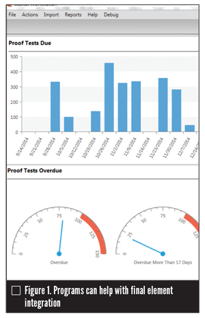
Studies2 have indicated that both material selection and process variations can cause failure mechanisms that lead to additional torque requirements for moving mechanical devices. These mechanisms include formation of oxide from temperature levels rising that results from temporary, random process upsets and galvanic corrosion. These conditions can result from dissimilar metals in the presence of electrolytic fluids. This is because the changes are unique to each final element, and modeling installation is difficult without actual field testing data. Software programs greatly facilitate the collection of this data. (Figure 1)
ROOT CAUSE ANALYSIS
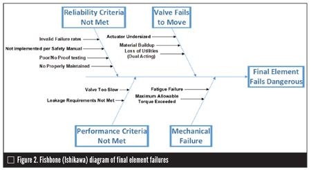
Performing root cause analysis helps in understanding what steps are needed to eliminate sources of failure for final element assemblies. Several valid techniques for conducting a root cause analysis exist, including using a fishbone diagram. Figure 2 shows a fishbone diagram of dangerous final element failures.
The failures shown here are not from lack of understanding of the basic failure modes or of the performance of devices in the field, which leads to the question: “Why are these weaknesses making their way into SIL-rated assemblies?”
CAPTURING FINAL ELEMENT REQUIREMENTS
The requirements for a final element often are not specified with sufficient clarity and detail, which are needed to facilitate a well-designed and verifiable subsystem. Some have argued a gap in the coverage of IEC [International Electrotechnical Commission] 61511 and IEC 61508 exists that leaves final elements in a no-man’s land zone between the standards. Another potential cause is familiarity that leads to overconfidence in knowing what needs to be documented and evaluated for final elements. This second cause stems from a general understanding of what can fail in final elements and the feeling that too much focus on specification and testing is not a good use of time and resources.
Examining how IEC 61511 and IEC 61508 are typically used in relationship to integrated final elements shows that such action can lead to under-specification of final elements. IEC 61508 is used extensively to evaluate the suitability of devices for safety-related applications. In this context, the focus is on ensuring devices can perform in accordance with published or agreed-upon product functions and performance specifications.
IEC 61511 typically is used to specify the functional and integrity requirements from an operational level. These requirements are high level and can include factors such as:
- Valve will close on trip
- Valve will have a leakage of Class III or less
- Valve will close in one second
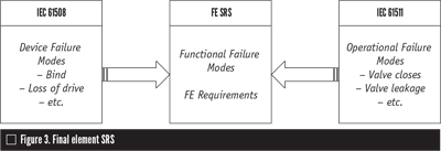
IEC 61508 addresses the device failure modes while IEC 61511 addresses the operational failure modes. Either of the standards can be implemented in a way that captures the functional failure modes or the under-specified area between what the end user or the equipment supplier specifies.
What’s needed is treatment of final elements as bespoke systems—the choice of which standard applies is a secondary consideration since either of them can be applied in a way that will improve the safety reliability of integrated assemblies. Figure 3 shows how the final element safety requirement specifications (SRS) can bridge the gap between two standards.
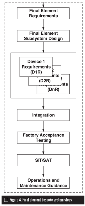
- Final element requirements
- Final element subsystem design
- Device requirements
- Integration
- Factory acceptance testing
- Site integration testing/site acceptance testing
- Operations and maintenance guidance
Figure 4 depicts the steps for the final element bespoke system.
CONCLUSION
While challenges exist in achieving the high reliability required in safety applications, the industrial world is making steady progress towards reaching that goal. Through a combination of increased understanding of true torque requirements and better specification and validation of final element performance requirements, significant progress can be made.
CHRIS O’BRIEN is executive vice president for exida.com LLC (www.exida.com). Reach him at cobrien@exida.com. Loren Stewart is senior safety engineer for exida. Reach her at lstewart@exida.com.
The information in this article will be included in an upcoming book: Final Elements in Safety Instrumented Systems; IEC 61511 Compliant Systems and IEC 61508 Compliant Products, which is written by O’Brien and Stewart.
References
- Benjes, Henry H., Operator Torques for Butterfly Valves www.awwa.org
- Bulowski, Julia V., Documentation of Recommended Revisions to Failure Rates and Modes Database in Support of Product FMEDAs, exida.com LLC, Sellersville, PA, December 2018
RELATED CONTENT
-
Valves in Oxygen Service
In his presentation at VMA’s 2017 Technical Seminar, Kurt Larson, a process control engineer for Air Products, spoke about the inherent danger of the oxygen production business and how it is particularly important for end users and valve manufacturers to work closely together.
-
An Overview of Butterfly Valves
A key advantage of selecting a butterfly valve is the reduction of space and weight to a system compared with other options such as ball, check, globe or gate valves.
-
An Overview of ASME B16.34-2017
The content of American Society of Mechanical Engineers (ASME) Standard B16.34 is essential to those who deal with flanged, threaded and welded-end valves.


 Unloading large gate valve.jpg;maxWidth=214)


