New Technologies Solve Severe Cavitation Problems
An advanced anti-cavitation control valve design enabled by 3D metal printing solved a power plant’s severe cavitation problem and dramatically improved its bottom line.
#controls #materials
Applications with very high pressure drops often create control valve problems, requiring solutions created by combining innovative valve design and advanced metallurgy. These issues are even more pronounced in a power plant where magnetite (iron oxide) is often present in boiler feedwater (BFW) systems. In these cases, the damage caused by cavitation is compounded by erosion and plugging created by the magnetite.
Emerson engineers were engaged to address a vexing control valve application problem of this nature at a local power producer in Wisconsin. The solution required a novel design created using additive technology, specifically 3D metal printing.
APPLICATION ISSUES
The BFW pump supplies high pressure water to the boiler or heat recovery steam generator to maintain proper drum level and pressure, producing significant pressure increase across the pump. This pressure increase also produces an associated increase in feedwater temperature across the pump. If a constant minimum flow through the pump is not maintained, the temperature will rise to a point where substantial damage to the pump may occur.
Therefore, a recirculation system is needed to protect the BFW pump. During startup or low flow conditions, a BFW recirculation valve opens to maintain a minimum flow through the pump to avoid pump damage from overheating. Under these conditions, the pressure drop across the valve is very high, nearly 2500 PSI. A back pressure regulator is installed downstream of the valve to take some of the pressure drop and reduce the strain on the valve (Figure 1).
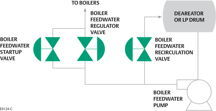
Figure 1. A boiler feedwater recirculation valve is installed on the discharge of the boiler feedwater pump, and it opens during plant startup to avoid deadheading the pump. Photo credit: Courtesy of Emerson
The water coming from the low pressure (LP) drum is over 300°F, and this elevated temperature combined with the very high-pressure drop can create cavitation within the valve. While cavitating conditions tend to damage valve internals, the problem is made much worse by magnetite in the feedwater, which further erodes the valve internals and plugs the small passages inside a typical drilled hole or torturous path anti-cavitation valve trim. This plugging reduces flow capacity, and thus plug and seat erosion from cavitation and particulate erosion can damage both the seat surfaces and valve plug seals, preventing the valve from shutting off tightly.
If this type of damage occurs, the valve has a constant minor leak when it is fully seated, reducing water flow to the rest of the process. This leakage causes further damage to the valve, and to the downstream regulator, which should see no flow under normal operating conditions. In the worst case, there is insufficient feedwater to the boiler or the heat recovery steam generator to meet load demand, causing a plant derating and lost revenue.
ANTI-CAVITATION TRIM TO THE RESCUE?
The internals of a control valve in these types of very high-pressure drop applications are specially designed to eliminate damaging cavitation. Cavitation occurs when liquid flows through a valve and falls below the vapor pressure as it passes through the valve seat at high speed.
Once the liquid passes through the valve trim, the velocity slows and the pressure recovers, collapsing the vapor bubbles in the fluid. As each bubble collapses, it emits local shock waves that damage the seat, plug and walls of the valve — as well as the downstream piping. A cavitating valve sounds like it has gravel passing through it, and the resulting damage reinforces this observation.
Anti-cavitation trim eliminates damaging cavitation by taking a number of smaller pressure drops (stages) as the liquid passes through the valve. By taking several smaller drops, the pressure stays above the vapor pressure of the fluid, thereby eliminating damaging cavitation (bottom dashed line in Figure 2).
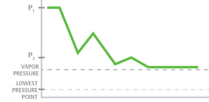
Figure 2. Cavitation in a control valve can be avoided if the pressure drop is taken in small steps and kept above the vapor pressure of the liquid. Photo credit: Courtesy of Emerson
This type of trim is usually fabricated using hardened, high-strength alloys and many small holes (Figure 3, left). As the plug moves up and down inside the cage, the holes are exposed, and each takes a pressure drop, avoiding any pronounced pressure dips as the liquid passes through the valve.
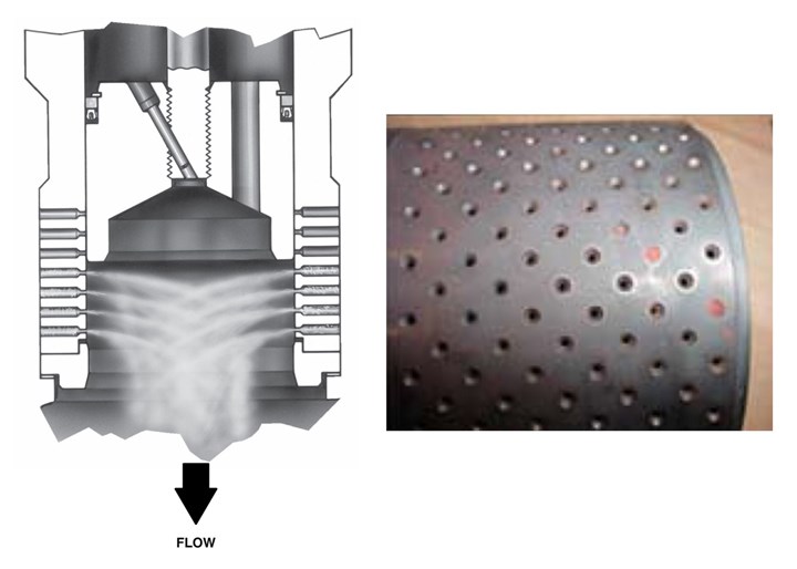
Figure 3. A typical anti-cavitation design (left) employs a number of small holes in the trim to take the pressure drop in small steps. However, in this application, magnetite was plugging the holes (right), reducing capacity. Photo credit: Courtesy of Emerson
The installed control valve had three-stage trim, which would ordinarily work very well in this application. However, this particular plant had significant magnetite in the BFW, which tended to plug the small holes in the trim. This reduced the overall valve capacity, while damaging the primary seating surfaces and valve plug seals (Figure 3, right).
Rather than allowing water to pass only when open during start-up or low flow conditions, the valve had a minor leak continuously, and this flow damaged the valve even more.
CASCADING PROBLEMS
The issues associated with this one valve created a chain of other problems. The valve trim was designed to minimize cavitation but damage from magnetite within the valve resulted in:
- Valve leakage created a constant flow/vibration through the downstream backpressure regulator, damaging it over time.
- Valve leakage constantly eroded and damaged the control valve internals, as well as the downstream piping.
- As the valve leaked, the damage got worse, creating still more leakage, and required the plant to rebuild the valve twice a year on average.
- The leak recycled BFW back to the LP drum rather than to the process. This loss in BFW capacity forced the BFW pump to run at ever higher capacity to make up for the loss in flow, wasting energy.
- Eventually, the pump was driven to run at 100% capacity, wearing out the pump much sooner than normal, requiring overhauls with increasing frequency.
- When the valve leakage became too high, the pump could not keep up and a duct burner had to be shut down for lack of BFW, reducing plant capacity and resulting revenue.
The plant tried installing mesh strainers upstream of the valve, but these plugged and had to be pulled and cleaned regularly, creating a maintenance problem. Clearly, a better solution was needed.
INNOVATIVE DESIGN ADDRESSES ISSUES
After evaluating the process conditions, engineers recommended a recently introduced anti-cavitation control valve design with dirty service trim (DST). As can be seen in the comparison pictures in Figure 4, the trim has very small holes subject to plugging in applications with a high degree of particulates, while the DST can pass entrained particulates from ¼ to ¾ inches. The seat is also protected from the major flow path in the DST design — so it lasts much longer, even in erosive, plugging service — ensuring tight shutoff.
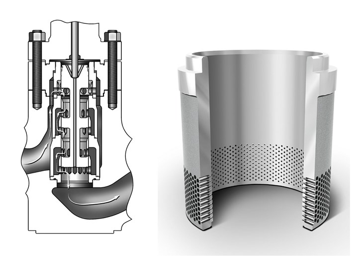
Figure 4. This anti-cavitation trim (right) has a large number of very small holes. Dirty service trim (left) has much larger flow paths, allowing up to ¾-inch particulates to pass through. Photo Credit: Courtesy of Emerson
The DST design was quickly developed utilizing a new method of manufacturing called additive technology, specifically a subset of this technology referred to as 3D metal printing. While 3D printing was originally limited to plastics, it has advanced rapidly. Lasers can now be used to fuse metallic powders into virtually any shape imaginable, including some designs that cannot be made using standard machining methods.
Historically, very intricate parts could not be made of high-hardness materials because they were too brittle. However, 3D metal printing allows parts to be created from very high-grade, high-hardness materials, regardless of the level of intricacy. In this case, the new DST valve (Figure 5) was manufactured using R31233 cobalt chrome (like alloy 6), so the new internals were much harder and erosion resistant than the valve trim originally installed.
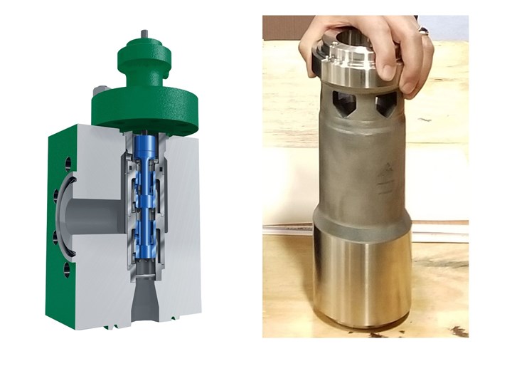
Figure 5. DST Valve design and R31233 cobalt chrome internal components enabled by additive technology (3D metal printing). Photo credit: Courtesy of Emerson
REMARKABLE RESULTS
The results were dramatic and very profitable for the plant. The new DST trim eliminated the leakage and erosion issues, generating the following bottom line profit improvements:
- Savings of $20,000 per year due to reduced backpressure regulator repairs (includes parts, labor and scaffolding)
- Elimination of $100,000 per year in control valve/piping repairs (includes parts, labor and scaffolding)
- BFW pump required capacity was lowered, cutting energy costs
- BFW pump overhaul interval extended by four years
- Most importantly, the plant now runs all its duct burners at full capacity, generating an additional $7,000,000 per year in revenue.
These improvements were the result of close cooperation between the control valve manufacturer and the plant engineers throughout the process of identifying the specific problem, creating a solution, and verifying its effectiveness in this challenging application.
CONCLUSION
Recent advancements in additive technology, specifically 3D printing, have allowed for the development of new valve designs and prototypes with unprecedented speed. New critical service valves can now be fabricated with increased capabilities for challenging process conditions.
This technology also allows parts, even those with complex geometries, to be fabricated from much higher hardness materials, so even existing valve trims can be upgraded to solve erosion and resulting internal damage problems. For power and other process plants struggling with a critical service, high-pressure drop application, this option should be considered.
ABOUT THE AUTHORS
Mark Nord is a control valve solution architect, Global Industry Sales at Emerson’s Flow Controls Business Unit. He has a BS in Mechanical Engineering from the University of North Dakota and more than 30 years of power industry experience, including over 25 years of control valve experience across all major industries.
Steve Zinda is a key account manager for Novaspect, an Emerson Impact Partner. He has a BS Mechanical Engineering and an MBA, both from UW-Madison. Zinda has 30 years of power industry experience, and 20 years of experience providing Emerson solutions to improve plant performance and reliability.
RELATED CONTENT
-
Understanding Torque for Quarter-Turn Valves
Valve manufacturers publish torques for their products so that actuation and mounting hardware can be properly selected.
-
Selecting Non-metal Materials for Valve Components and Coatings
Non-metallic materials are commonly used for valve components, and the selection of non-metallic materials for valve design and for application-specific conditions is critical to ensuring product reliability.
-
Creating a Standard for Severe Service Valves
Severe service valves are offered in several standard designs, including non-return, isolation and control types.


 Unloading large gate valve.jpg;maxWidth=214)