
Produced by


Published July 25, 2023
Proper sizing, material selection and monitoring are as important as ever.
By Kevin Jackson, New Energy Specialist, Baker Hughes

Photo Credit: iStock/audioundwerbung
Hydrogen has a long history in the energy market — from powering the first internal combustion engines over 200 years ago to becoming an integral part of the modern refining industry. When we think about hydrogen applications, most people think of hydrogen used in refineries to either remove sulfur from gasoline, diesel fuel and other refined products, as a catalyst to stimulate chemical reaction, or as a fuel for furnaces that generate steam for several refining processes. It is important to note that hydrogen is a gas that must be treated with respect, particularly when it comes to material selection. If not, the safety risk associated with using improper materials can be catastrophic and pose a long-term safety hazard.
As we move to a greener world, hydrogen is becoming an increasingly common fuel and is expected to be used in various applications. These applications include the blending, in different percentages, of hydrogen with natural gas commonly 20%/80%, to produce a gas for gas-fired power generation that reduces CO2 output by approximately 6-7%, or in transportation either as drop-in fuels, hydrogen gas cells, or in liquid form for vehicles that require longer range.

The ecosystem of the hydrogen economy continues to expand.
Photo Credit: U.S. Dept. of Energy
Hydrogen can be produced in four basic ways. In the refinery, hydrogen is traditionally produced from natural gas, oil or coal by steam methane reforming or by gasification, with approximately 96% of today’s hydrogen produced using this process. Electrolysis is the fourth method, and today represents about 4% of total hydrogen produced globally.
When it comes to sizing and configuring control valves for hydrogen gas and liquid applications, control valve engineers must exercise caution. This is especially true now, as hydrogen is being generated and transported in large quantities around the world in various forms including hydrogen gas, hydrogen pure liquids and organic compounds that either absorb hydrogen or mix it with nitrogen to produce ammonia. All these forms of hydrogen require proper pressure and temperature control to make them viable as pure hydrogen or as a carrier to move it to areas where hydrogen cannot be manufactured locally in sufficient quantity to meet the local demand.
There are five key areas to consider when determining the size and configuration of a control valve for use in hydrogen, as well as when configuring isolation and safety valves.
Hydrogen embrittlement (HE), also known as hydrogen-assisted cracking or hydrogen-induced cracking (HIC), is a complex process involving several distinct contributing micro-mechanisms, familiar to anyone who has worked in the upstream sector. However, in more recent years, it has become widely accepted that HE is a complex issue that can be a result of improper material selection and environmental conditions, metal hydride formation, phase transformations of the hydrogen and a variety of other factors without always being able to identify a single cause. The result of HE is a reduction in ductility due to the absorption of the very small hydrogen atoms.
Steels with a tensile strength of less than approximately 145 ksi (1000 MPa), or with a Rockwell hardness of less than HRC 32, are the alloys that are not generally susceptible to hydrogen embrittlement. Temperature must also be considered because HE is maximized around room temperature in steels, but most metals are relatively immune to hydrogen embrittlement at temperatures above 150°C (302°F). Pressure should also be considered, as the hydrogen partial pressure at which maximum embrittlement occurs is estimated to be between 300 and 1500 psi (20 and 100 bar).
It should be noted that hydrogen embrittlement occurs in steels and similar metals at relatively low hydrogen concentrations, depending on the temperature and pressures. Generally acceptable materials for hydrogen service include austenitic stainless steels, aluminum alloys, copper and copper alloys. Nickel and most nickel alloys should not be used since they are subject to severe hydrogen embrittlement. Gray, ductile and malleable cast irons should also not be used for hydrogen service.
Tests such as ASTM F1624 can be used to rank alloys and coatings during materials selection to ensure that the threshold of cracking is below the threshold for hydrogen-assisted stress-corrosion cracking. Tests should be conducted during quality control to qualify materials being produced in a rapid and comparable manner. Standards such as NACE MR-0175 for upstream exploration and production, and NACE MR-0103 for refinery environments, can help define and specify control valve requirements for hydrogen gases.
When considering materials, also consider materials used for diaphragms and sealing. While research and testing are ongoing, the knowledge of hydrogen compatibility with polymers continues to undergo extensive field tests. Users understand the principles of explosive decompression from gases, but hydrogen adds another layer of complexity, especially for diaphragms. Packing materials for control valves may seem straightforward in terms of selection, spiral wound, PTFE or graphite, but special attention to temperature and pressure must be considered for hydrogen applications.
A fugitive emission is defined as the unintentional and/or undesirable emission, leakage or discharge of gases or vapors from pressure-containing equipment like faulty or incorrectly applied valves.
There are two main types of emissions that impact the environment, air quality and human health: greenhouse gas emissions (GHG) and air pollutant emissions. For valves, we are concerned with greenhouse gas emissions.
Fugitive emission testing is an umbrella term for a wide variety of differing test procedures and methods used to test and evaluate the integrity of the external leakage of valve stem seals/packings and body joints of control valves — globe, rotary and regulators.
The test needs to be a direct reflection of the actual service conditions, from cryogenic to ambient and extreme high temperatures and pressures. The most common test standards used for control valves are ISO-15848-1 and 2, ANSI/ISA S93.00.01, ANSI/FCI 91-1, TA-Luft/VDI 2440, API-622, API-624 and API-641. Some companies have their own test procedures, for example, Shell SPE 77/300 and Shell SPE 77/312. When specifying, configuring or purchasing control valves, the appropriate standard should be used with proof of third-party witnessing certificates that covers the correct stem diameters, materials and test gas. It should be noted that any witnessed test should not only include the steam packing but all body joints as well through the cycle and temperature variations.
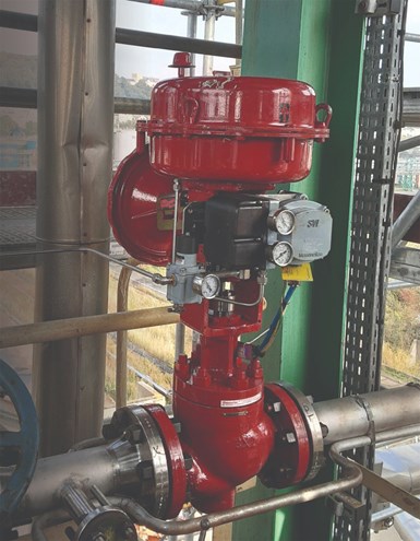
Photo Credit: Baker Hughes
Approximately 60% of fugitive emissions come from valves, and as much as 80% of the leakage per valve originates from its stem packing. Other sources from the valve are bleed or exhaust ports from solenoid valves, positioners, and other control accessories. To avoid the development of leaks, regular testing and maintenance go a long way in preventing fugitive emissions. For gaseous fugitive emissions, regular use of gas detection devices is useful as it helps detect the source of such emissions.
The performance of a valve’s safety features is measured in terms of the Probability of Failure on Demand (PFD). Through this calculation, you get a Safety Integrity Level (SIL) as an indication of system reliability and integrity, and it’s measured on a scale of 1 to 4 (4 being the safest and most unlikely to fail, but rarely used). This is not a requirement to have when selecting a valve type or manufacturer, however, it does provide a level of confidence that the supplier is reputable, and a measure of performance and safety based on international industry standards.
However, if the failure of the control valve does not place a demand on the Safety Instrumented System (SIF), for which it is a part, but could place a demand on any other associated SIF, additional analysis will be required.
The process of control valve sizing is a procedure where the fluid dynamics of the system are matched to the performance characteristics of the valve. This selects a control valve of an appropriate size and type that best meets the needs of managing flow within the process system. Each control valve manufacturer, together with some independent software companies, has developed its own platforms for valve sizing based on the ANSI/ISA-75.01.01 and IEC 60534-2-1 standards.
Obviously, all control valves are slightly different from each other in terms of their unique design characteristics. Although they all use these industry standards, each manufacturer has certain nuances because of the unique design profile of certain components of the valve that can affect the outcome of the valve sizing evaluation. Each sizing should be accompanied by the manufacturer’s sizing data sheets. Independent sizing software can give the ideal size and performance data, but it is generic.
Reputable control valve manufacturers carry out verification tests to ensure that the calculated performance stated with their valves will match, within a minimal acceptable tolerance, the actual valve performance when it is installed. Additional tests to verify precise flow rates, noise generated, capacity and pressure drop can be carried out by request.
Along with the above, when sizing and selecting control valves for use on hydrogen the sizing is affected by several factors:
Great care needs to be taken when selecting control valves. Always look for a manufacturer who can provide evidence and examples of true understanding of the nuances of hydrogen applications for the safest and best results.
As the world moves forward in IIoT and smart systems, control valve diagnostics is now a key part of monitoring and managing control valves in the new era. This involves using the positioner to monitor the valve’s health and gather data about its position, conditions and performance to improve plant efficiency and process uptime.
Understanding changes in the valves operating conditions and performance is critical to acting before a breakdown occurs. If you are not measuring and tracking a system, you are only guessing and missing your optimal performance.
Any online valve diagnostics should consist of key performance indicators (KPIs) which are continuously monitored while the valve is in service, providing real insights into actual operating performance of the valve system without the need to take a process offline.
To get the most out of your system and processes, it is ideal to be brand agnostic and have a valve asset management system that can track assets from all manufacturers throughout the entire lifecycle of all the valves in the plant.
Hydrogen is light, storable, energy-dense and produces no direct greenhouse gases. But for hydrogen to make a significant contribution to a clean energy transition, it needs to be adopted by all industries as a key fuel to reduce greenhouse gases. As the industry continues to grow, as always it is imperative that valves used in hydrogen applications are properly sized and are constructed of the proper materials for the applications where they will be used.
There are still many hurdles to overcome including safety, regulatory, scalability and lowering costs. Consider hydrogen compared with where LNG (liquified natural gas) was 20 years ago and the transformation that has taken place in production, transporting and offloading. Certainly, the challenges are different and currently not all the processes and equipment exist to take full advantage of hydrogen and its new role in the world, but the future of hydrogen seems secure as a major fuel source.


June 5, 2026
Why engineered mounting kits are critical to valve automation integrity.
April 7, 2026
Simple automations can create big gains on the shop floor.
April 3, 2026
