
Produced by


Published October 3, 2022
There are many applications where the globe valve outshines other designs, so the future is still bright for these long-time favorites of the flow control industry.

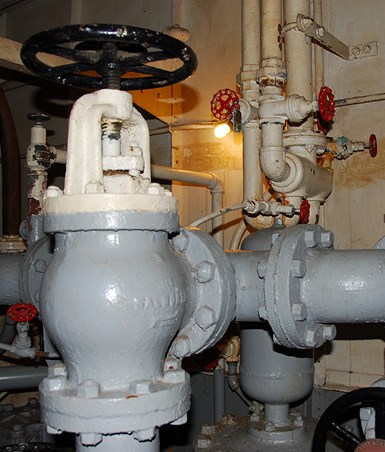
Vintage globe valve design with rotund body
Photo Credit: All images credit: Greg Johnson
Globe valves are used everywhere today and have been a fixture on the fluid control landscape for 200 years. The globe valve’s primary reason for existence is to regulate the flow of fluids, however, there are still applications where complete blocking of flow is also handled by globe valve designs. The common hose spigot which dots the outside of houses and commercial buildings is a good example of globe valve on/off and regulating usage.
The lifeblood of the industrial revolution was steam and water, but these potentially powerful fluids needed to be controlled. The first valves called upon to do that job efficiently were globe valves. The design was so effective and popular that the first patents obtained by most of the major legacy U.S. valve manufacturers (Crane, Powell, Lunkenheimer, Chapman and Jenkins) were for globe valve designs.
Although the globe valve can be used as a block or isolation valve, it is designed to regulate flow in the partially open position, while gate valves are designed to be used in either the fully opened or fully closed position. Care in design selection should be taken when considering globe valves for on-off isolation service valves because of the difficulty in maintaining a tight seal against a strong force pushing up on the disc. With flow coming from the above-disc direction, positive sealing is assisted by the force of the fluid and is easier to attain.
The regulating function of globe valves makes them perfectly suited for control valve applications, where positioners and actuators attached to the globe valve bonnet and stem makes very accurate regulation possible. In these applications, they are referred to as “final control elements” and provide workman-like service in a variety of fluid control applications.
AN INDIRECT FLOW PATH
The globe gets its name from its original rotund design, a design that still hides its unique and somewhat convoluted flow path. Unlike fully opened gate or ball valves, a fully opened globe valve still provides a lot of friction or resistance to fluid flow, with its zigzagging up and out pathway. This angled flow creates fluid friction, which in turn slows down flow through the valve.
Flow rates through valves are measured by their flow coefficient, referred to as “Cv”. The Cv for the same size gate and globe valve will be vastly different since the gate valve offers little flow resistance while in the open position.
The globe valve closure mechanism, called a disc or plug, can be machined to many different shapes. By changing the shape of the disc, the rate of flow through the valve as it is opened can be varied greatly in proportion to the number of turns of the stem. The more common or “conventional” curved type disc design is used for most services as it opens more for a given movement (rotation) of the stem than other designs. The V-port disc design is used for fine throttling through a wide range of opening percentages and is adaptable to all size globe valves. The needle disc design is used for very-fine flow regulation but is usually only available in smaller sizes. When absolute shutoff is required, a soft-seating elastomer insert can be installed in either the disc or the seat.
GLOBE VALVE TRIM
In globe valves, the parts that provide the actual component-to-component closure are called trim. The components that make up the trim in a globe are the seat, disc, stem, backseat and sometimes the hardware that connects the stem to the disc. Correct trim design and materials selection are critical for correct operation and longevity of any valve, especially globe valves due to their high fluid friction and convoluted flow path. As the seat and disc move closer together, the velocity and turbulence across them increase. This elevated velocity combined with the corrosiveness of the fluid can cause the trim to be damaged, resulting in a valve that leaks badly in the closed position. Sometimes the defect is what looks like a thin slice in either the seat or disc, which is called wiredrawing. This initial small leak path can widen and become a major leak if not repaired promptly.
On smaller bronze globe valves, the trim is usually the same material as the valve body, or in some cases a similar bronze alloy with greater strength. On iron globe valves, the most common trim material is bronze. The designation for this trim on iron valves is “IBBM,” which stands for “iron body, bronze mounted.” Steel valves are offered in a variety of trim materials, with usually one or more of the trim components being a 400-series martensitic stainless steel. Hard facings such as Stellite are also used, as well as 300-series stainless steels and copper-nickel alloys, such as Monel.
Globe valves are available in three basic patterns. The most common is the “T” pattern, where the stem is perpendicular to the pipeline flow. The angle pattern is similar to the T pattern, but the flow is turned 90 degrees in the valve to allow the angle valve to serve as both a flow control device and 90 degrees piping elbow. The angle pattern globe valve is still commonly used on the top of boilers and is also the pattern used for the final output regulating valve on oil and gas “Christmas trees.”
The third design is the “Y” pattern design, developed to reduce the turbulence that takes place in the body of a globe valve as well as provide a more rigid design for on/off applications. In this type of globe, the bonnet, stem and disc are slanted at a 30-45 degree angle, resulting in a straighter flow path and less fluid friction. This reduced friction also means potentially less erosive damage to the valve, as well as better overall flow characteristics for the piping system.
BONNET DESIGNS VARY BY APPLICATION
Globe valves come in a variety of bonnet designs, and each has its place and purpose. For small bronze valves, the inside-screw-rising-stem design is the most popular. In this design, the stem threads are contained within the pressure/fluid envelope of the valve bonnet. This design is easy to manufacture, but it does have one drawback — the threads are exposed to the process fluid. This means that the critical stem threads could be damaged if exposed to corrosive liquid or gas. Normally, this type of valve is used for water or low-pressure steam so that is not an issue.
Bonnet designs where the stem threads are outside of the pressure/fluid envelope are much preferred on valves larger than NPS 2, or when a valve is in corrosive service. The most common of these designs is called the outside screw and yoke, also known as OS&Y. It is the primary design for larger industrial globe valves.
The body/bonnet connection on globe valves comes in various configurations. Both threaded connections and union bonnets are found on the smaller bronze valves, while the bolted bonnet is found on most steel and iron globe valves. The pressure seal bonnet is used on high-pressure, high-temperature globe valves, such as the Y-pattern design.
STOP-CHECK VALVES
Globe valves and boilers have literally and figuratively been connected for over 150 years. The first valve on any boiler output line is quite often a stop-check valve, also known as a non-return or boiler stop valve. The stop-check is actually two valves in one: a globe valve for regulating flow, and a check valve for preventing backflow. To make the non-return function occur, the disc on a stop-check is not attached to the stem but is guided in the valve bonnet and allowed to freely move up and down when the stem is raised. This allows the flow rate to be regulated, but when backflow occurs, the disconnected disc functions as a piston check valve and quickly closes, preventing reverse flow into the boiler. If tighter shutoff is required, the stop-check stem may be lowered by closing the stem, preventing movement of the disc to the fully open position. In addition to regulating boiler output, the stop-check valve is also used for other applications where combining a check valve and globe valve makes sense for the piping designer.

LARGE OD GLOBE VALVE ISSUES
Due to some testing requirements, large globe valves can present challenges during the seat-test phase of hydrostatic testing. The problem occurs when globe valve bonnets flex because of the hydrostatic test pressure being transferred from the area under the disc, to the stem, yoke and then to the bonnet. While globe valves are designed to be operated primarily in the partially open position to regulate flow, they are nonetheless required to pass a stringent 110% of rated-working-pressure hydrostatic seat test in some testing standards.
The problem is a lack of stiffness in the bonnets of these low-pressure, large globe valves. For the most part, wall thickness requirements come from the American National Standards Institute (ANSI) B16.34, “Valves- Flanged. Threaded, and Welding End,” but that is often not enough section thickness to keep bonnet flexing from occurring. Most of these basic globe valve designs and patterns were created back when the required American Petroleum Institute (API) 598, “Valve Inspection and Test” seat test for globe valves was only 90 psi air. Prior to the sixth edition of API 598, “Valve Testing and Inspection,” published in 1990, when the 90-psi air low pressure test was the required test procedure for globe valve seat testing, the problem did not exist.
On large, low-pressure-class valves this can cause the disc to lift away from the seat a few thousandths of an inch as the pressure is increased, thus causing leakage. The easy solution is to add more thrust on the stem (tighten it) as it rises. This usually solves the problem, however, the initial closure torque is often exceeded during this operation. Due to flexibility in the valve bonnet, large diameter, handwheel-operated globe valves may require secondary re-torquing when used in on/off service. This re-torquing may also be required during hydrostatic testing.
To counter the problem without adding extra thickness or ribbing to the bonnet, many manufacturers will provide hammer-blow handwheels, manual bevel-gear operators or powered actuators as standard on these larger valves. The use of these methods usually works well but does mask the actual degree of force applied to close the valve.

API GLOBE VALVE STANDARD — API 623
API has created a relatively new globe valve standard, API 623, “Steel Globe Valves — Flanged and Butt-welding Ends, Bolted Bonnets,” which requires wall thicknesses greater than ANSI B16.34 and similar to those in API 600. The additional thickness requirement is designed to address potential corrosion and erosion issues that often occur in petrochemical and refining applications, but this added thickness also helps to address the bonnet flexibility issues that can occur during hydrostatic testing and high-pressure closure applications.
Another point that is addressed in the 623 document is the need for stronger stems to provide tight sealing when certain corrosion-resistant alloys are used for stem construction. Many austenitic stainless-steel materials such as 316 stainless steel are chosen for stems in highly corrosive fluid applications. However, these materials are sometimes significantly weaker than the 410 stainless steel stems usually specified as standard. This requirement resulted in the stem diameters in the document being appreciably larger than non-API 623 globe valve stems.
While the tried-and-true globe valve is still being manufactured in huge quantities all over the world, newer quarter-turn designs such as the butterfly and ball valve have taken much of the previous market share. However, there are still many applications where the globe valve outshines other designs, so the future is still bright for these long-time favorites of the flow control industry.


June 5, 2026
Why engineered mounting kits are critical to valve automation integrity.
April 7, 2026
Simple automations can create big gains on the shop floor.
April 3, 2026
