
Produced by


Published May 21, 2024
These spring-loaded valves provide overpressure protection for downstream equipment.
By Wai Loon Cheong, Baker Hughes
In the past two issues of this publication, we have covered the fundamental operating principles and applications for spring-loaded safety relief valves and pilot-operated safety relief valves (POSRV). In this last installment of the three-part series, we will focus on the fundamental operation of safety valves and common applications.
A safety valve (SV) is a spring-loaded pressure relief valve actuated by the static pressure upstream of the valve, characterized by rapid opening or “pop” action. A safety valve is normally used on compressible fluids, primarily steam. These devices are typically certified to protect the system within 3% overpressure, which is the rise in pressure above the maximum allowable working pressure (MAWP) of the equipment being protected.
Typically, the spring is exposed and visible without the need for valve disassembly. Safety valves come in two predominant designs — the robust side-rod construction (Figure 1), suitable for high-pressure and temperature applications, and the versatile yoke design, used for lower pressure and temperature applications (Figure 2).
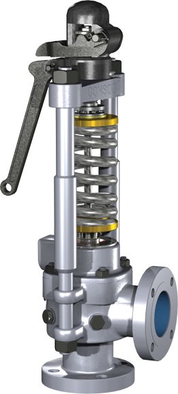
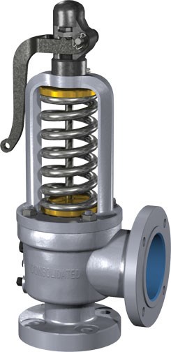
Figure 2: Yoke design.
When operating pressure acting from the inlet of a safety valve is less than the spring force pushing down, the safety valve is closed as shown in Figure 3. For a safety valve to maintain seat tightness, the operating pressure should typically be equal to or less than 95% of the set pressure.
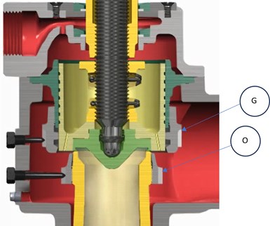
Figure 3: Safety valve in closed position.
When operating pressure increases until the simmer point, as shown in Figure 4, steam will move past the seating surfaces into the huddling chamber. Flow restriction in the secondary annular orifice formed between the upper adjusting ring (G) and lower adjusting ring (O) causes pressure to build up and act over a larger area, creating an additional force to overcome the spring force. The disc will then move away from the seat bushing and the valve will “pop” open at set pressure.
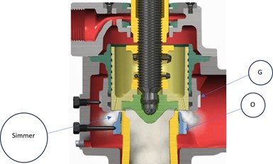
Figure 4: Safety valve “simmer point.”
Once the safety valve has opened, the position of the upper adjusting ring forces the steam to change direction, creating additional lift. These additional forces cause the disc to achieve full lift. Full lift can be attained by proper location of the upper adjusting ring (G) and lower adjusting ring (O), respectively. When full lift is attained, as shown in Figure 5, the lift stop (M) rests against the cover plate (P) to eliminate hunting, thus adding stability to the valve. When the safety valve is in the open position, steam is bled into chamber (H) through two bleed holes (J) in the roof of the disc holder. Similarly, the spindle overlap collar (K) rises to a fixed position above the floating washer (L). The area between the floating washer and the spindle is thereby increased by the difference in the two diameters on the overlap collar. Under this condition, steam (H) enters into chamber (Q) through the secondary area formed by the floating washer (L) and the overlap collar (K) on the spindle, then through orifice (N) and escapes to atmosphere through the pipe discharge connection (R). Additional steam will flow through the area between the floating washer (L) and the overlap collar (K).

Figure 5: Safety valve at full lift position.
When closing, as shown in Figure 6, the spindle overlap collar (K) moves down into the floating washer (L), thereby effectively reducing the escape of steam from chamber (H). The resulting momentary pressure building up in chamber (H), at a rate controlled by orifice (N), produces a downward thrust in the direction of the spring loading. The combined thrust of the pressure and the spring loading results in positive and precise closing. During closing, the force of trapped steam on the upper side of the disc holder is utilized to assist the spring in forcing the disc back down onto the seat. Cushioning of the closing is controlled by the lower adjusting ring (O).

Figure 6: Safety valve closing.
Two side rods are located outside of the safety valve body and installed so they are away from the high temperature of the boiler and the side rod temperatures remain relatively constant. The two side rods allow the thermal expansion of the safety valve body, caused by the high temperature of the boiler, without having a negative effect on the safety valve performance. Thus, spring-loaded models are relatively constant, and set pressure is predictable and does not vary with changes in the heat flow pattern.
The thermodisc (marked P in Figure 6) stits on the seat bushing and makes up the seating surface of the safety valve. Often made of Inconel for its superior corrosive resistance, it minimizes distortion to the spindle/disc contact area under temperature, load or impact during safety valve actuation. Thus, the safety valve can achieve a reliable seat tightness of 95% of set pressure. The thermodisc has a unique design with a thin flexible lip which enables the seat to retain flexibility, especially under steam conditions, where it is usually higher in temperature and pressure. The thin flexible lip design enables the disc temperature to quickly equalize with the steam temperature, reducing distortions caused by the steam throttling to atmosphere. This lip design enables the system pressure to assist the mechanical loading. A line contact at the sealing surface of the seat bushing is created which improves the seat tightness. The critical seating area remains constant, ensuring a consistent safety valve set pressure. The thermodisc provides a low spindle bearing point for the spring force to transmit below the horizontal seating line of the safety valve. It equalizes spring force distribution to the safety valve seat area and minimizes the natural tendency for the disc to assume a horizontal tilted position. It remains concentric to the bushing centerline which assures reseating to the original position and prevents damage caused by any misalignment.
Full lift at set pressure can be achieved by rapidly venting steam through the cover plate (marked P in Figure 5). During discharge of the safety valve, the cover plate redirects the steam to a safe location. Thus, it isolates the spring from the steam temperature, which reduces spring relaxation.
Blowdown can be achieved by adjusting the upper adjusting ring, along with the lower adjusting ring (marked O in Figure 5), to have a short simmer and a good clean pop at set pressure. By properly fine-tuning of the overlap collar (marked K in Figure 5), 3% blowdown can be attained through pressure-assisted closing.
Safety valves are typically provided for the power industry. However, they are also used in other industries such as refining/petrochemical, chemical, pulp and paper, metals and mining, and textiles where boilers are used for power generation. Some common applications for safety valves include boiler drums, superheaters, reheaters, economizers, feedwater heaters and in other plant applications.
As this series concludes, the journey through the basics of pressure relief valves sheds light on the different valve types that are out there safeguarding our industrial landscapes — spring-loaded safety relief, pilot-operated safety relief and safety valves — and their operational and application differences. These devices are a critical last line of defense for the protection of people and property from overpressure events in systems.
All images in this article are copyright of Baker Hughes.
ABOUT THE AUTHOR
Wai Loon Cheong is the valves training leader for Baker Hughes. He has more than 20 years experience, and has worked in a variety of roles at the company.


June 5, 2026
Why engineered mounting kits are critical to valve automation integrity.
April 7, 2026
Simple automations can create big gains on the shop floor.
April 3, 2026
