Standards for Actuator/Gearbox Flanges
“Many variations in valve and actuator dimensions and characteristics have come into play especially now that we have worldwide vendors,” said Paul Souza, training manager at AUMA Actuators in a presentation at the Valve Manufacturers Association Virtual Valve Forum in November 2020.
#VMAnews #standards #actuators
We have equipment coming from the United States and from other manufacturers around the world. Sometimes they bolt together. Sometimes they don’t due to mounting flange incompatibility. We replace a lot of equipment in the field. Sometimes you are replacing only a portion of the actuator.” Properly mating the old and new components can be difficult at times.
Standards are intended to assist in making sure these parts go together, “but like every standard I’ve ever run into,” Souza said, “there are always exceptions.” To complicate matters, the standards in the U.S. are different from the standards in the rest of the world, in large part because of the different measurement systems (metric and imperial).
Souza offered an example comparing the actuator/gearbox flange standards from the Manufacturers Standardization Society (MSS) used in the U.S. and the equivalent standards from the International Organization for Standardization (ISO).
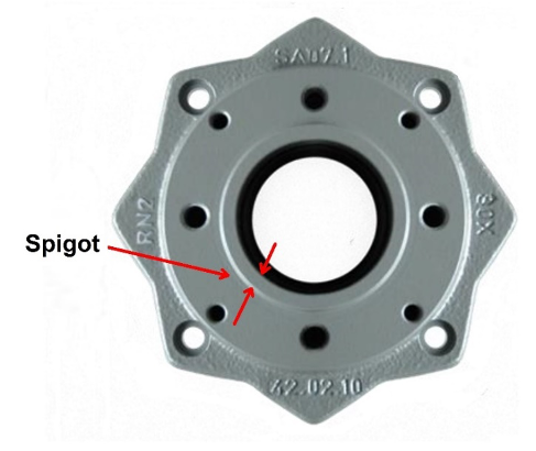
Since the actuator, gearbox and the valve are mounted together, Souza said, each gearbox and valve requires a suitable mechanical connection. The actuator/gearbox flange enables this connection. It also provides an alignment feature used to ensure correct centering on the valve flange. Variously called the spigot, pilot, centering ring or alignment boss (Figure 1), this feature engages with a mating feature on the valve flange to provide positive alignment.
MSS AND ISO ACTUATOR/GEARBOX FLANGE STANDARDS
For the spigot to provide alignment it needs to engage with a mating feature of the right size and geometry on the valve flange.
It is important to understand that actuators/gearboxes made to different standards may have spigots of different sizes and different forms for the same size component.
It is also important to note that there are different standards for multi-turn and part-turn (quarter-turn) actuators and gearboxes:
- ISO 5210 and MSS SP-102-1989 apply to rotary or multi-turn devices
- ISO 5211 and MSS SP-104-2017 apply to part-turn (quarter-turn) devices.
Flanges on devices made to the MSS standards are designated FA flanges; those made to the ISO standards are F flanges.
DIFFERENCES BETWEEN MSS AND ISO STANDARDS
In some respects, FA and F flanges are similar. For a given size, they have the same bolt pattern and bolt circle diameter.
Other aspects are different. For example, FA flanges per the MSS standard use imperial fasteners; F flanges per the ISO standard use metric fasteners
A critical difference is in the size of the spigot, which may be different depending on which standard it was built to. For a size 16 multi-turn flange, the spigot outer diameter is 5 in. (127.0 mm) for an MSS flange and 5.11 in. (129.8 mm) for an ISO flange.
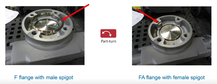
An even more significant difference occurs among part-turn devices. The form of the spigot is different: the MSS standard specifies a female spigot, while ISO specifies a male spigot (Figure 2).
Table 1 summarizes some of the differences and similarities among the multi- and part-turn MSS and ISO flange standards.
MAKING IT WORK
The spigot engages with a counterbore or groove on the valve flange, centering the actuator with respect to the valve. To achieve centering, the alignment feature on the valve flange and the spigot on the actuator side must fit closely and allow the flanges to mate together flush. If necessary, machine the valve’s mounting flange to accept the spigot on the actuator flange, Souza said.
Misalignment can cause wear on parts such as the valve stem and gears, causing premature failure. The packing tolerances on today’s valves make alignment especially important, Souza said.
“Valve makers manufacture valves throughout the world and if you’re not specific in your request you may get an F flange or an FA flange,” said Souza. Your valve needs to match. This may be particularly problematic when it comes to replacing equipment.
Before all the flange standards were implemented, valve and actuator flanges could be quite different, he said, and even today there are exceptions to what the standards specify. Most manufacturers can accommodate these differences for you if you alert them to your needs. Alternatively, your automation company or machine shop can make adapters.
In any case, following good assembly practices and making use of the alignment features provided according to the standards, Souza said, will support a long, trouble-free life for your valves.
Barbara Donohue is a freelance technical writer and journalist and former Web editor of VALVE Magazine.
RELATED CONTENT
-
The Diverse Role Valves Play in the Chemical Industry
The chemical industry is extremely diverse with more than 60,000 known products. Like all process industries, the chemical industry needs valves designed for safe, efficient and reliable process operation.
-
How the EPA's Emissions Rule May Impact Actuator Choices
The move toward net zero emissions by 2050 was just released as part of the COP28 meeting in Dubai.
-
Valve Basics: Electric Actuator Controls
Electric valve actuators control the opening and closing of valves. With a motor drive that provides torque to operate the valve, these actuators are frequently used on multi-turn valves such as gate or globe and also on ball, plug and other quarter-turn valves.


 Unloading large gate valve.jpg;maxWidth=214)