Linear Actuators for Automating Gate Valves
Most professionals in the valve industry are already familiar with the use of linear actuators to operate globe valves.
#gate-globe-check #actuators
LINEAR ACTUATORS
A linear actuator may be any device that generates linear motion, as compared to a conventional motor that produces a circular motion. The primary advantage of a linear actuator is that many applications require linear motion, including valves and dampers. The simplest possible design for a linear actuator is a piston moving within a cylinder, a configuration that has only one moving part. James Watt made the first practical steam engines during the 1770s, which required tightly fitting pistons in cylinders. Modern linear actuators may be powered in a variety of ways, although the ones used to operate valves typically use hydraulic or pneumatic power sources.
Linear hydraulic actuators provide more precise control over the piston’s movement because liquids are virtually incompressible. Hydraulic fluid is pumped into the cylinder to push the piston forward and removed to pull it back. The piston’s displacement occurs only along its axis, making this movement linear. A hydraulic car jack is one of the most common examples of a linear hydraulic actuator, which is typically controlled by a hydraulic pump.
Pneumatic linear actuators are similar in principle to a hydraulic actuator except that they’re powered by compressed air rather than hydraulic fluid. As a result, their movements are less precise than a hydraulic actuator’s since air is compressible. Thus, a pneumatic linear actuator generally isn’t the best choice for moving a large amount of weight. In addition, air compressors are difficult to transport due to their size and make a great deal of noise while operating. That said, the primary advantage of a pneumatic actuator is that it can be powered with compressed air, which is readily available in many industrial environments.
GATE VALVES
A gate valve opens by lifting a barrier, or gate, out of a fluid’s path. The gate faces are usually wedge-shaped to increase the pressure against the sealing surface, although they can also be parallel. The biggest advantage of a gate valve compared to other designs is that it creates almost no resistance to fluid flow when the gate is fully open. Furthermore, gate valves take up little space along the pipe’s axis. The primary disadvantage of gate valves is that the size of the flow path changes in a nonlinear manner as the gate moves, so the flow rate isn’t consistent with stem travel. Fluid flow can also cause vibrations when the gate is partially open for some gate valve designs.
The most common application for a gate valve is to simply open and close a pipe completely rather than regulate fluid flow. They’re typically used for larger pipes with a diameter of at least two inches since their design is simpler than other types of valves. However, gate valves become harder to operate at high pressure because the fluid pressure pushes the gate against its guiding rail. Large gate valves may require a bypass controller to reduce fluid pressure on the gate before the gate valve itself operates.
Applications where minor leaking isn’t critical may use gate valves without an additional sealing ring on the gate or seat, typically in heating or sewer pipes.
STEMS
Gate valves with actuators use a threaded stem to connect the actuator to the gate via a drive nut around the threads, allowing the nut to be turned with a hand wheel or motor. The stem may be classified as rising or non-rising, depending on which end is threaded.
Rising stems are attached directly to the gate, allowing them to be raised and lowered with the gate. This design provides the operator with a visual indication of the valve’s position. Gate valves used with linear actuators will typically have rising stems.
Non-rising stems are fixed to the actuator and threaded into the gate, allowing the stem to rotate with the actuator. This design conceals the gate’s motion within the valve, so it may use a pointer threaded onto the stem to indicate the valve’s position. Non-rising stems are primarily used in applications with limited vertical space.
MODIFICATION
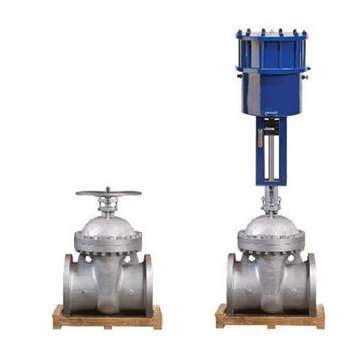
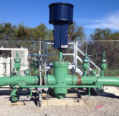
Attaching a linear actuator to a gate valve is fairly straightforward. It requires the hand wheel and drive nut to be removed, exposing the threaded stem. A coupling must then be installed to connect the stem to the actuator’s piston rod, allowing the actuator to move the stem up and down. Figure 1 shows a manual gate valve; Figure 2 shows linear actuators installed on underground gate valves.
SIZE
Linear actuators provide thrust rather than torque, which is a direct function of the cylinder’s size since the actuator’s thrust is the product of the pressure the hydraulic fluid or air exerts and the cylinder’s surface area. A higher required thrust thus increases the actuator’s minimum size, while a higher supply pressure reduces it. An actuator should therefore use the highest supply pressure available at the site in order to minimize cost, which is largely driven by cylinder size.
The best practice in determining the minimum size requirement for a linear actuator is to use the thrust needed in actual operating conditions. Calculating the required thrust from the maximum differential pressure rating for the valve as defined by ANSI will typically result in a higher thrust than would be needed in practice, unnecessarily increasing the cost of the actuator.
SUMMARY
Pneumatic and hydraulic linear actuators have proven their adaptability in many applications outside the valve industry. Their compact profile is ideal for tight piping runs and their simple yet robust design makes linear actuators reliable under a range of operating conditions. Linear actuators offer an effective automation solution for gate valves with rising stems.
Cooper Etheridge is CEO at Automation Technology, Inc.
RELATED CONTENT
-
Effective Check Valve Selection and Placement for Industrial Piping Systems
When planning a check valve installation, the primary goal is to achieve a valve and piping system that offers the longest service life at the lowest cost.
-
Valve Selection for Bypass of Control Valves: A Case Study
A bypass line including a bypass valve is typically installed to provide continuous operation in case of regular maintenance of a control valve.
-
The Misunderstood Check Valve
Too often this valve is unjustly blamed when problems occur, but the real culprit is its use in the wrong applications.


 Unloading large gate valve.jpg;maxWidth=214)

