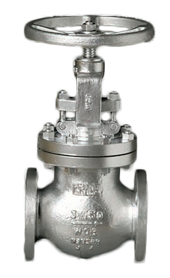
Stop Check Valves
Stop check valves are vital to several industries to protect boilers and other equipment.
#basics #gate-globe-check #automation
Because of this, having a stop check valve is like having two valves in one. The internal disc, which is not attached to the stem, performs as a lift check allowing it to freely move up and down when the stem is raised to adjust the opening and closing. This controls the flow rate, but when backflow occurs, the disconnected disc functions as a piston check and quickly closes, thus preventing reverse flow into the boiler. If needed, the stem can be manually lowered for flow to be stopped or completely shut off.
END USE OF STOP CHECK VALVES
These valves are mostly used in power plants, in applications such as boiler circulation, steam generation and boiler feed water, turbine cooling, starter water and safety systems. They also are used in other applications where piping designers want to combine the properties of a globe and check valve. Such applications might include high-temperature service, heat recovery steam, high-pressure safety service, geothermal service, utilities, petroleum production and refining, safety systems, shutdown cooling, and hydrocarbon processing.
In boiler applications, valves and boilers have been connected for over 150 years. The valves used are so critical that the American Society of Mechanical Engineers (ASME) Boiler and Pressure Vessel Code covers how valves should be used. The first valves on a boiler output line are usually stop-check valves, which are known here as non-return valves or boiler stop valves. They are vital when more than one boiler is connected to the main steam header, and they should be installed in the pipeline between each boiler and the header. They also should be placed so that the pressure in the boiler is under the disc.
Another boiler application is to use the stop check as a blowdown valve. The blowdown valve allows removal of excess water from a boiler, which is required occasionally. Blowdown stop check valves are still in use on stationary boilers.
DESIGNS
These valves are available in two basic pattern designs, T pattern and Y pattern. In the T pattern, the stem is perpendicular to the pipeline. This allows the internal disc to move up and down vertically in the valve. The weight of the disc helps it to close quickly, providing minimal reverse velocity when the valve closes. However, because of its weight, it requires a higher flow velocity to get the valve fully open and could also add to the valve pressure loss.
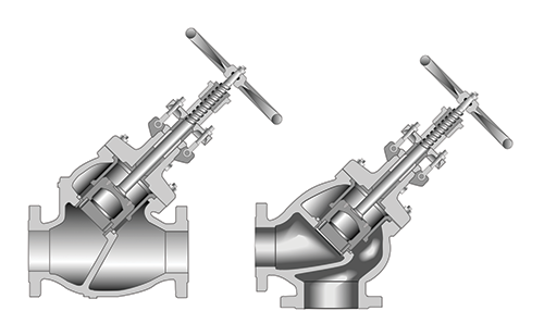
The newest design, which is similar to the T pattern, is the Y pattern, where the stem and disc are angled at 30 to 45 degrees. This pattern design is most commonly used on top of boilers and comes in a straightway or an angle flow path. The Y pattern, with its angled stem and disc, allows a lower full-open flow velocity. However, more attention to the disc guiding is required for trouble-free operation.
The straightway design results in a straighter flow path, which reduces turbulence and creates less fluid friction. That means less potential for erosive damage to the valve, which converts to lower pressure loss and better overall flow characteristics for the piping system. These types of valves should be installed in horizontal (Figure 2) or vertical (Figure 3) lines for upward flow.
The angle valve design is used for upward-to-horizontal (Figure 4) or horizontal-to-downward (Figure 5) flow. But in both cases, the flow is turned 90 degrees in the valve to allow the angle valve to serve as both a flow control device and a 90-degree piping ell.
Since valves have a cylindrical-shaped floating disc member that is the only pressure-actuated part, it is important they be sized to provide proper full disc lift during the valve’s service life. If too large, the disc may flutter, increasing the valve wear rate and limiting its service life. If the valve is too small, it will provide a much higher pressure loss and high velocity, which also could reduce service life. If the disc is light and properly guided, it can provide maximum lift at minimum velocities for quick opening and low pressure loss. Additionally, the disc should be designed to prevent spinning, which results in low wear and long service life.
End connections for most valves are either flanged to ASME B16.5 or butt weld conforming to ASME B15.25. Other connections can be furnished as specified by the customer.
FEATURES
In boiler applications, valves are designed to perform several very important functions including:
- They act as automatic non-return valves. In case a boiler fails, the valve can prevent gross backflow of steam from the main header to the boiler.
- They isolate a boiler when ceasing to fire and when the boiler is blown down. The valve automatically closes to prevent backflow of steam to the boiler.
- They assist in returning the boiler to operation after a shutdown.
Although the check valve feature should not be relied upon for primary shut off, it can restrict the backflow from the header into the boiler that has been shut down and opened or suffered a pressure containment blowout.
STANDARDS
Many of the standards on stop check valves are related to globe valves, and there are many of those types of standards. API published a standard on globe valves recently that discusses valves larger than NPS 2. API 623, which was published in 2013, covers stop check valves. Subjects covered include:
- The pressure is to be equalized in the bonnet above the disc to the downstream side.
- Design should have a suitable disc or bottom guiding to allow the disc to move freely during check valve operation. This will prevent any failures of the flow return prevention feature of the valve.
- Testing is to be in accordance with the requirements of API 598 for both globe and check valves and meet the acceptance criteria of both types of tests. Valves must meet both valve test criteria on the shell as well as the seat leakage requirements
- Valve design has to be suitable for installation with the stem in the vertical orientation or where the stem is within 45 degrees of vertical orientation.
Other industry standards that are applicable include:
- SME B16.5—Pipe flanges and flanged fittings NPS 1/2 through NPS 24 Metric/Inch
- ASME B16.34—Valves‒flanged, threaded and welding end
- API 598—Valve inspection and testing
- API 602—Steel gate, globe and check valves for sizes dn 100 (NPS 4) and smaller for the petroleum and natural gas industry
- API 623—Steel globe valves—flanged and butt-welding ends, bolted bonnets
- BSI 1873—Steel globe and globe stop and check valves (flanged and butt-welding ends) for the petroleum, petrochemical and allied industries
- ISO 12149—Bolted-bonnet steel globe valves for general-purpose applications
- MSS SP-80—Bronze gate, globe, angle and check valves
- MSS SP-85—Gray iron globe and angle valves, flanged and threaded ends
- MSS SP-118—Compact steel globe and check valves (chemical and petroleum refinery service)
MATERIALS
As with globe valves, the trim components in stop check valves are usually bearing the brunt of the fluid flow during the closure operation. Industry standards allow for end users to specify the trim materials required for specific applications. In these standards, trim items include the body and disc seating surface and stem. Additional items can be specified by the end user or can be the manufacturer’s standard material.
Choosing the correct trim materials is critical for maximum operation and longevity of any valve, especially stop check valves, which are similar to globe valves, and have high fluid friction and intricate flow path. As the disc moves closer to the body seat surface, the velocity and turbulence increases, creating a potential for cavitation and erosion, which could result in a leaking valve and excessive wear thereby reducing service life. These types of defects can appear as a thin slice in the body seat, disc or both. This initial small leak path can widen and become a major leak.
On some bronze valves, the trim is either the same material as the valve or a similar bronze alloy with greater strength. On iron valves, the usual trim material is bronze. The industry designation for this trim on iron valves is “IBBM,” which is defined as “iron body, bronze mounted.” Steel valves are offered in a variety of trim materials, as needed by the service. However, they usually will have one or more of the trim components made of 13% chrome martensitic stainless steel. Hard facings such as Stellite are also used, as well as 300 series stainless steels and copper-nickel alloys. Positive shutoff and long seat life is provided by an integral hard surface seat. A popular trim in steel valves is API trim #8, 13% Cr./hardface.
CONCLUSION
Stop check valves provide a comparatively economic and efficient solution where isolation, regulation and prevention of backflow are required performance characteristics for a piping system.
Carlos E. Davila, PE is product manager,‒Engineered Check Valves for Crane ChemPharma & Energy. Reach him at cdavila@cranecpe.com.
RELATED CONTENT
-
Valve Basics: Electric Actuator Controls
Electric valve actuators control the opening and closing of valves. With a motor drive that provides torque to operate the valve, these actuators are frequently used on multi-turn valves such as gate or globe and also on ball, plug and other quarter-turn valves.
-
Understanding Torque for Quarter-Turn Valves
Valve manufacturers publish torques for their products so that actuation and mounting hardware can be properly selected.
-
Air Valves in Piping Systems
Liquid piping systems are prone to collecting air from incoming fluids, pumps and connections.


 Unloading large gate valve.jpg;maxWidth=214)