Knifegate Valve Maintenance and Repair
Knife gate valves are used to provide isolation in various applications including oil sands slurries, pulp stock, waste water and power generation.
#maintenance-repair #water-wastewater #gate-globe-check
1. Adjust the packing once a month.
2. Lubricate the stem and stem nut every three months. This should be done using a grase gun at the grease fitting at the top of the yolk.
3. Lubricate the gear operator once a year.
PACKING
When knife gate valves are not in use over a long period of time, the valve should be cycled at least every six months, and if in storage, the packing should be loosened to extend the life of the packing.
It’s also important to tighten the packing gland as needed. When adjusting packing on valves with four or more bolts, it is best to tighten the bolts evenly on both sides of the packing gland using the cross torque method. Normally just a small amount of tightening is required. Do not over tighten to stop a leak; try to adjust the packing gland down evenly to avoid the possibility of the gland rubbing on the gate as it moves.
With regular inspection and lubrication, which depends on the cycle count and the chemicals at play, the operator will see when packing or seats need replacing. If maintenance is necessary, safety comes first:
1. Shut off all operating lines to the valve.
2. Isolate the valve completely from the process.
3. Release process pressure.
4. Drain the process fluid from the valve.
REPLACEMENT PACKING
Standard repacking kits are available from knife gate manufacturers and their distributors. Packing kits include the necessary packing to ensure a tight seal. When ordering packing kits, be sure to specify the valve model number, seat type and type of valve. Safety first: Release pressure from the valve and make sure it is closed.
1. Remove packing gland nuts and bolts.
2. Raise gate to full open position.
3. Pull up the packing gland to the top of the gate and secure it to the top of the gate.
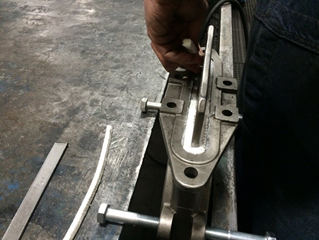
4. Using a packing hook or screw driver, remove all the old packing.
5. Carefully clean the packing box.
6. Using a pre-cut packing kit, insert packing one row at a time into packing box. Tap down each row of packing into place using a flat bar tool. Packing joints should be located 180° apart.
7. Pull packing gland down and tighten nuts and bolts using cross torque method. DO NOT OVERTIGHTEN.
8. Bring valve up to working pressure and tighten the packing gland just enough to stop any leaks or drips. Over tightening of the gland will result in reduced packing life.
SEAT REPLACEMENT
To replace a seat, first remove the valve from the line.
Bidirectional Perimeter Seats
1. Disconnect the stem clevis from the gate and remove the yoke and stem assembly. Remove the packing gland, packing and valve gate.
2. To remove the seat it will probably take a good firm grip on the seat and the metal wire insert with a pair of vice grips, and possibly have the aid of a come-along to pull the old seat from the valve body. In the bottom of the valve, the seat groove has retainer ledges and the rubber seat must be pulled through this narrow opening.
3. To install the new seat and repack the valve, the opposite procedure is required. First place the new seat into the valve body seat cavity by bending the seat into a horseshoe shape and insert into the seat cavity. Take a three- or four-foot length of flat bar approximately 3/8-inch x 2- or 3-inches wide and tap the seat as firmly as possible into the bottom of the valve and along the sides.
4. When the seat is in place with the ends on each side protruding above the packing box, insert the valve gate. Install the yoke and stem assembly, and move the gate to its bottom position, ensuring the seat is pushed into its retainer groove all around the bottom and along the sides.
5. When the seat is definitely in place, remove the yoke and stem assembly. Repack the valve, placing packing strips on each side of the gate for the full length of the packing box. Make sure the packing is cut long enough and fits firmly against each end of the packing box. When the valve gland is packed to its fullest, take a hacksaw and cut off the excess rubber seat that extends above the packing box on each side.
6. Install the packing gland and reinstall the yoke and stem assembly.
7. Stroke valve through one full cycle and assure both easy operation and no rubbing of the body or packing gland on the gate.
8. Under pressure, tighten the packing gland bolts only enough to stop packing leakage.
Unidirectional O-ring Seats Replacement Procedure
To change the O-ring seat seal, access to the valve seat is required either by removing the valve from the line or by access to the valve seat in the line.
1. Stroke the valve to the full open position.
2. Remove old O-ring and scrape out any residue that has accumulated in the O-ring groove in the seat. Be sure the O-ring groove is completely cleaned out before proceeding.
3. Install the new O-ring as follows:
- Note that the new O-ring diameter is somewhat smaller than the O-ring groove diameter. This allows the O-ring to be slightly stretched when it is installed in the groove. Lubricate the groove with some light oil. The O-ring will have a bonded joint. Be sure the joint is installed at about the 6:00 o’clock position.
- Push an approximate 1- to 2-inch section of the O-ring into the groove at the 12:00 o’clock position. The groove is a dovetail shape so it is wider at the bottom of the groove than at the top. The O-ring may be a little tight at the top.
- Gently stretch out the O-ring, and find the point on the O-ring that is exactly one half the distance from the 12:00 o’clock position. Push approximately 1 to 2 inches of the O-ring into the groove at the 6:00 o’clock position. Be sure that there are equal lengths of the O-ring between 12:00 and 6:00 o’clock positions, on both sides.
- Now do the same at the 3:00 o’clock position and the 9:00 o’clock position, always being sure the lengths are equal on both sides of the points where the O-ring is pushed into the seat.
- Keep doing this by pushing the O-ring into the groove, halfway between the two points where the O-ring has already been installed.
- After the O-ring has been completely installed, check that it is evenly distributed in the groove. If there are places where the O-ring seems thicker than in others, then use a smooth round piece of wood or plastic to even out the inconsistencies.
- Lubricate the face of the seat and the O-ring with silicone grease.
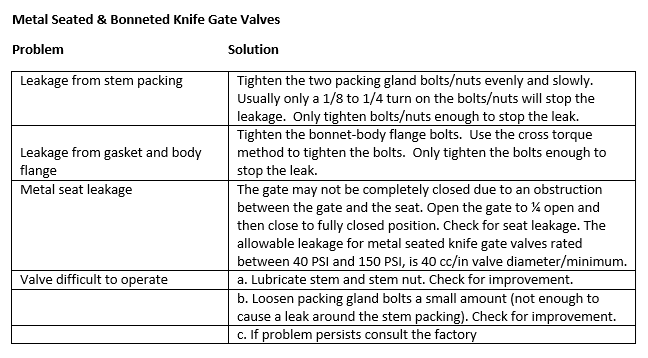
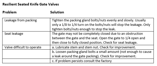
TROUBLESHOOTING CHART
While the schedule and procedures for maintaining knife gate valves are fairly straightforward, there are details and operational issues that will add or change maintenance requirements. By being aware of these variables and adjusting maintenance accordingly, valve life can be extended and total cost of ownership reduced.
Vikki Pynenburg is marketing manager at Lined Valve.
RELATED CONTENT
-
Which Gate Valve is Best for Today's Waterworks Systems?
A historical perspective may provide the answer.
-
Check Valve Installation Considerations to Maximize Process Performance
Key considerations in successful check valve performance.
-
Ancient Roman Valves
The story of water supply in the ancient Roman Empire is grand.


 Unloading large gate valve.jpg;maxWidth=214)