Because biopharmaceuticals are produced using living organisms, and the drugs produced are used in humans and animals, the cost of contamination is very high, and sterilization of the process system is critical.
To ensure sterilization, temperature measurement and control practices are employed that verify steam sterilization occurs on time without fail. If the temperature is not within predetermined limits, temperature validation alarms occur. How does thermostatic steam trap operation affect the occurrence of temperature validation faults? What new technologies are available to mitigate common SIP problems?
Such questions are addressed in this article.
WHAT GOES INTO SIP
To begin, let’s briefly review some fundamentals of process equipment SIP and the operating principles of sanitary balanced port thermostatic steam traps.
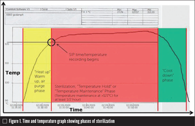
SIP is a timed sterilization of the upstream and downstream biopharmaceutical production train using clean steam. It is part of a five-step sanitization routine that occurs after every production batch (Figure 1).
SIP ensures every square inch of the production train that comes into contact with drug substance inputs, the drug substance itself and the final drug product is “sterilized” to ensure no microbiological activity exists in the system.
Clean steam, which is created using ultra-purified water, is circulated through all the process tubing and equipment during SIP, entering large vessels through spray balls embedded in the vessels’ ceilings.
SIP is a temperature-validated process, meaning that the sterilization event must be proven by measuring the temperature and recording that data. The minimum sterilization regimen requires injecting clean steam into all piping and vessels for at least one-half hour after that equipment reaches a minimum temperature of 250°F (121°C). If the temperature ever falls below that minimum during this temperature hold period, a temperature validation fault is recorded, the fault remediated, and SIP procedures must be repeated.
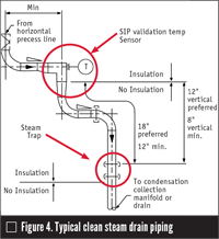
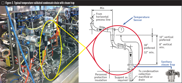
Validation temperature sensors (usually resistance temperature detectors) are placed at the condensate outlets (drain lines) at the bottom of process equipment skids to make sure the sterilization temperature meets the specific regimen designed for the process system. The sensing elements are most frequently designed with integral sheathes and tri-clamp connections and inserted into a mating tri-clamp connection on a tee in the drain line. Normally, the sensors are located 12−18 inches (300–450 millimeters) upstream of the clean steam trap where the condensate exits the piping or vessel (Figure 2).
Recorded time/temperature data (Figure 1) is stored in a programmable logic controller, distributed control system or stand-alone database for later use by company quality engineers and auditors.
THERMOSTATIC STEAM TRAP OPERATION
VALIDATION TEMPERATURE ALARMS
A validation temperature alarm occurs if the temperature measured in the condensate drain line (Figure 4) ever falls below 250°F (121°C). If that occurs, SIP must be stopped and the root cause of the temperature deviation corrected. Most validation temperature alarms can be traced to two root causes. They are both related to condensate back-up upstream of the steam trap.
All sanitary thermostatic traps require installation of a minimum length of tubing between the trap inlet and the validation temperature sensor to account for this buildup of condensate (Figure 4). If a thermostatic trap requires significant subcooling before the bellows begins to contract and open the trap, clean steam condensate will back up in the tubing upstream of the first trap and may wet and cool the validation temperature sensor. If that occurs during temperature maintenance (in other words, after the system heats up to at least 250°F (121°C)), a temperature validation alarm occurs when the sensor is cooled below that value.
Note that condensate backup is a common occurrence during heat-up (before the tubing is heated to the minimum 250°F (121°C)) because the amount of condensate produced can be significant. However, temperature validation does not officially begin until after the system being sterilized reaches its validation design temperature above the minimum temperature. At that point, the amount of steam required to keep the system at temperature and the associated condensate load is dramatically less. This is why it’s important to choose a trap that has enough capacity to handle the larger heat-up loads but with a low enough subcooling operation that condensate is never allowed to build in the tubing during temperature maintenance.
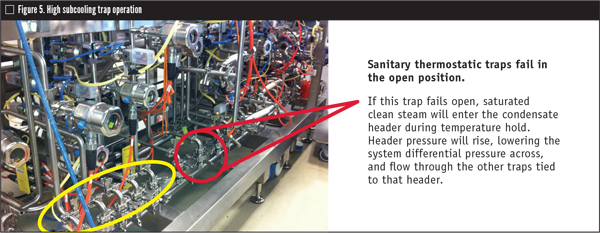
High subcooling trap operation (Figure 5) is one of the two most frequent causes of validation temperature alarms.
HIGH SUBCOOLING TRAP ALARMS
Another common cause for condensate back up and validation temperature alarms is failure of an adjacent trap on a common condensate header.
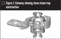
Balanced port thermostatic traps fail open when the stainless-steel bellows develops a leak and the fill escapes. Without its proprietary alcohol fill, the bellows can never expand to close the trap when exposed to steam temperature. The trap will remain open, allowing clean steam to pass through the trap into the condensate header. This is especially problematic during temperature hold (low condensate creation), because the increase in condensate header pressure can cause one or more adjacent traps to back up condensate. This backup occurs because the differential pressure across all of the traps connected to that header will be reduced (Figure 5). Reduced differential pressure will result in reduced flow in one or more of the adjacent traps on the common header. In smaller volume condensate headers (inner diameter is less than an inch), this low differential-induced capacity reduction can cause condensate backup significant enough to wet the sensor and cause a validation temperature alarm. (This is the reason that safety factors should be used when sizing clean condensate headers, i.e., they should be oversized.)
SIP PROBLEM REMEDIATION
Three common problems are encountered during SIP:
- Temperature hold validation alarms
- Slow condensate drainage
- Not getting up to temperature or not getting up to temperature fast enough (slow heat-up)
These problems are significant because each one delays completion of the sanitization regimen and therefore delays the productive utilization of the asset being sanitized. In other words, these problems cause lower annual production and revenue. (The potential loss is greatest in downstream purification and formulation assets because their batch cycle times are much shorter and usually more frequent.)
Most temperature hold validation alarms can be corrected or prevented by doing one or more of the following:
- Installing properly sized, low-subcooling traps in temperature-validated drain lines to minimize condensate backup
- Ensuring about 12−18 inches (300−450 millimeter) of three-quarter-inch uninsulated tubing is between the trap and temperature sensor to hold condensate backup.
- Properly sizing condensate headers so they can accommodate failed traps
- Immediately replacing failed traps on trap condensate headers. (An ultrasonic leak detector should be used periodically to test for and find failed traps during temperature hold.)
However, there are some installations where the solutions above are impossible to implement. For example, compact installations occur, particularly under vessels and equipment where there is not enough space to install a vertical and horizontal downcomber (drip leg) of sufficient length to prevent condensate from backing up and wetting the sensor. There also are some installations where unforeseen condensate load variations occur that overwhelm the condensate leg and the trap.
In those situations, two potential solutions can help:
- If the installation height for the required run of vertical tubing is not possible, the horizontal distance can be increased. Adding horizontal tubing distance provides volumetric cushion to prevent condensate from reaching the sensor. As long as some vertical tubing is immediately below the sensor to provide drainage, an increase in the length of slightly sloped horizontal tubing will provide the volume cushion needed to prevent sensor wetting and temperature validation alarms. (See ASME [American Society of Mechanical Engineers] BPE 2016 section SD-2.4.3 for drainability and slope recommendations.)
- If the height or horizontal space to install any significant horizontal or vertical tubing is not there (or not desired), then a subcooled condenser can be used to eliminate validation temperature alarms and improve condensate drainage during all phases of SIP.
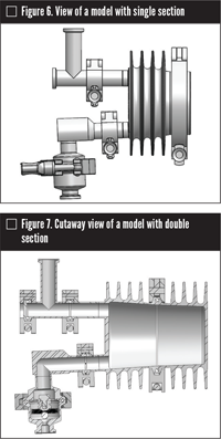
A sanitary subcooled condenser is a compact, finned, gravity drainable, condensate-holding chamber installed immediately downstream of the temperature validation sensor and upstream of the trap. In addition to optimizing installation space, it eliminates the possibility for validation temperature alarms and improves condensate drainage (Figures 6 and 7).
There are three significant benefits to these condensers:
- They allow the installation of temperature validated sensor/drip leg/trap assemblies in tight places, where there isn’t enough room to install the traditional 12−18 inches (300−460 millimeters) drip leg between the validation sensor and trap.
- The large chamber of the finned, volume collection chamber eliminates the possibility that condensate will back up and wet and cool the temperature sensor.
- The condensate is subcooled before it enters the thermostatic steam trap, contracting the bellows and further opening the trap orifice, thereby significantly increasing the trap’s ability to drain condensate quickly and lessening heat-up time.
The sanitary subcooled condenser has five times more radiant surface area than an 18-inch downcomber. The fins allow ambient air to completely enfold the condenser. The air is heated, rises and is displaced by cooler air from below. The radiant and convective heat loss combine to drastically sub-cool entering condensate by about 30°F (about 16,6°C temperature differential). The temperature difference causes the trap bellows to contract further, allowing a substantial increase in flow.
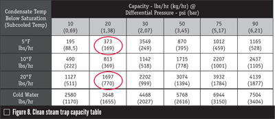
Looking at a clean steam trap capacity table (Figure 8) we can see trap capacity difference between 20°F (-7°C) subcooled condensate and 5°F (-15°C) at a trap differential pressure of 20 psi (1,4 bar). When condensate is cooled just an additional 15°F (-9°C), trap capacity increases 1,432 pounds per hour (lb/hr) (601 kilogams per hour (kg/hr)).
This significant increase in draining capacity lessens heat-up time.
SIP FOR LARGE VESSELS
Biopharm International addressed the subject of vessel steam sterilization and vessel SIP tubing design in an article published in 2003 (Designing a Shorter Vertical Leg for Sanitary Steam Traps, Sept. 01, 2006, by Richard Kal, George W. Page, Jr. Bio-Pharm International Volume 19, Issue 9). The article discusses the amount of clean steam required to heat up and hold sterilization temperature in various sizes of process vessels. It explains:
- A 40,000-liter (10,500-plus gallon) biopharmaceutical vessel may produce about 2500 lbs/hr (1134 kg/hr) of peak condensate during SIP heat-up and about 27 lbs/hr (12 kgs/hr) during SIP temperature hold.
- By contrast, a 600-liter (158-plus gallons) vessel will only produce about 100 lbs/hr (45,4 kg/hr) of peak condensate during heat-up and about 2 lbs/hr (0,91 kg/hr) during temperature hold.
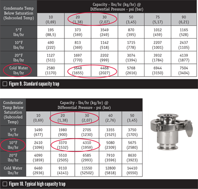
While 2,500 lbs/hr (1,134 kgs/hr) is within the load capacity of most standard steam traps (at normal SIP differential pressures), those traps can only handle that load at very high levels of subcooling (Figure 9). If the condensate is subcooled to the point where its temperature is 20°F (-7°C) or cooler than the steam saturation temperature, it is significantly backing up in the drain line upstream of the trap.
Most high capacity traps can handle large vessel heat-up loads at lower levels of subcooling (Figure 10) but they still drain slowly because the condensate will be subcooled 10°F (-12°C) at that load.
Since these high-condensate loads only occur during heat-up, there is no worry about validation alarms. However, it may manifest as slower heat-up time.
Removing condensate efficiently from vessels during SIP is important, but it’s not the only job a trap has to do. Clean steam traps also have to handle the large volume of air that will be displaced at the beginning of SIP.
For example, a 15,000-liter (about 4,000-gallon) biopharmaceutical vessel holds that same amount of air. As a general design rule, air should be removed in the first five minutes of SIP to minimize heat-up time (air acts as an insulator in steam tubing and vessels). Design should facilitate the removal of that air.
Lastly, during heat-up, air and condensate do not drain independent of each other. Both combine in a mixed phase flow that can further complicate draining and heat-up.
DESIGNING FOR SIZE
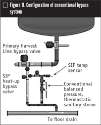
During SIP heat-up, air and condensate are diverted through the primary harvest line 3-way bypass valve directly to the drain.
When the SIP temperature sensor reaches about 203°F (95°C), the primary bypass closes, and the secondary bypass valve opens to direct the lighter condensate load through the steam trap.
CHALLENGES WITH CONVENTIONAL DESIGN
The piping bypass arrangement discussed in the previous section effectively handles fluids, air and condensate. However, two problems are associated with bypass use:
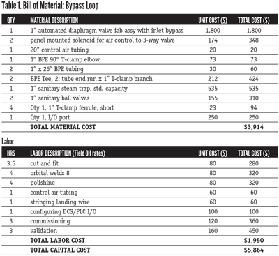
- High initial capital cost is involved: a conventional bypass loop consists of the components and labor shown in Table 1 above for a total installation expense of about $5,800.
A NEW SOLUTION
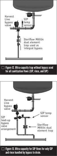
The problems associated with conventional bypass piping design resulted in creation of an ultra-capacity, dual element clean steam trap (Figures 12 and 13). It operates like this:
- Two bellows assemblies work together to handle sanitization liquids (rinse/CIP/rinse) and the heat-up and maintenance loads of larger vessels.
- During heat-up, both bellows are open, providing excellent capacity for eliminating air and condensate.
- The higher capacity bellows is designed to close when the vessel temperature is between 194°F and 212°F (90°C and 100°C). This allows the smaller, sanitary trap bellows to handle the smaller loads generated during temperature maintenance.
- No clean steam is lost during operation of the trap. Both bellows will close when the bellows sense saturated steam temperatures.
Innovations such as this by manufacturers will continue to improve the efficiencies of the SIP process.
KARL J. LUTKEWITTE is the product and sales manager, Steriflow Division, Richard Industries (www.richardsind.com). Reach him at Klutkewitte@richardsind.com or 513-533-7348.
RELATED CONTENT
-
Valve Basics: Electric Actuator Controls
Electric valve actuators control the opening and closing of valves. With a motor drive that provides torque to operate the valve, these actuators are frequently used on multi-turn valves such as gate or globe and also on ball, plug and other quarter-turn valves.
-
Rigging and Lifting of Large Valves
This article outlines the challenges of lifting large valve assemblies weighing several tons and illustrates the industrial rigging equipment and lifting operations typically used for these valves.
-
Understanding and Selecting Valve Flanges, Pt. I: Design and Standards
Because flanges allow the assembly and maintenance of system components without the need for cutting and welding pipe, they play an important role in piping systems.




 Unloading large gate valve.jpg;maxWidth=214)