The Dos and Don’ts of Isolating Pressure Relief Valves
Typically, isolation valves are used to block off a pressure safety valve (PSV) from system pressure, so that maintenance on the valve or related equipment can be conducted without a shut down.
#pressure-relief #maintenance-repair #automation
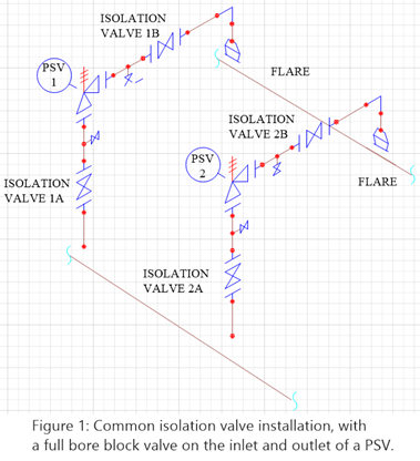
The use of isolation valves requires standard operating procedures (SOP) describing detailed steps for isolation. A recent analysis of an isolation valve installation reinforces the need for such a procedure and highlighted a previously overlooked source of overpressure. In this case, a major oil and gas producer had two spring-loaded pressure safety valves, PSV 1 (in service), and PSV 2 (stand-by spare), protecting a single pressure vessel with an isolation valve installed at both the inlet and outlet of each PSV. Inlet isolation valve is in position A, and the outlet isolation valve is in position B.
The Problem
The refinery experienced an overpressure event and PSV 1 began to leak. In order to perform repairs on PSV 1, operators began the process of switching the inline spare (PSV 2), into service by closing the isolation valve, 1B, at the outlet of PSV 1. Note, at this point, the vessel was no longer protected by any relief valve. We will discuss this further in the summary.
The closing of the isolation valve is a manual procedure and is both time-consuming and physically intensive. Because of this, the operators waited before they began the process of closing the inlet isolation valve (1A). In the meantime, the pressure between the discharge of PSV 1 and isolation valve 1B reached operating pressure which was above the MAWP of the bellows installed in PSV 1, which was 150 psig @100°F.
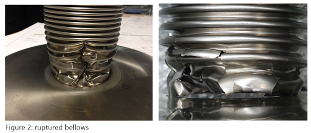
When PSV 1 was taken out of service and examined for maintenance, the operators noticed that the bellows had ruptured. The FES team was consulted at this point to help explain why the bellows had ruptured. Figure 2 shows examples of ruptured bellows.
Root Cause Analysis
In the course of diagnosing the cause of a relief system failure, a review of known system operating parameters was begun:
System Details:
Operating Pressure = 508 psig
Valve Set pressure = 638 psig
Total Back Pressure = 145 psig
MAWP of Bellows = 150 psig @ 100F
Nothing appeared to be amiss in the system details. The typical next course of action was to evaluate the discharge piping hydraulics and ensure that the built-up or superimposed backpressure was lower than the Bellows’ MAWP. No issues were found with either type of backpressure and it was confirmed the relief temperature was not reducing the MAWP by running the properties through a process simulator.
Operators disclosed that they would first close isolation valve B at the outlet and then close isolation valve A at the inlet. It is important to note that the shutoff for each isolation valve would sit for an extended period of time because this was a manual operation and the person would take a break after closing the first valve. It was found that the PRV was leaking severely when tested in the shop. This leak, in conjunction with the valve isolated at the outlet, created a new source of pressure on the discharge side of the PSV. Because this new source of pressure was in excess of the equipment operating pressure and far in excess of the MAWP of the bellows, the bellows ruptured.
Solutions
Solutions to prevent future bellows failure include revising the procedure on the sequence of operating the isolation valves. This problem would not have occurred had the operator closed isolation valve 1A and then isolation valve 1B, followed by opening the inlet and outlet bleed valves. This does not address the second issue which was that the system was unprotected for the duration of the isolation SOP.
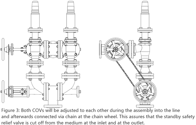
Another more comprehensive solution would be to install a properly configured change-over system which is designed for safe isolation of pressure relief valves. (Figure 3) A combination COV system would replace the isolation and bleed valves and integrate the existing relief valves. One of the aspects of the combination COV is that when one PSV is taken out of service for maintenance, both the inlet and outlet of that relief valve are isolated simultaneously. As was mentioned earlier, the previous SOP created an unprotected situation on the vessel. The combination COV solution would also ensure the vessel is protected at all times, providing the safest solution.
Summary
The use of isolation valves presents real risk to operators if either the shutdown procedures are not correct or if operators do not follow the procedure as described. Both situations can create a scenario where the system is either unprotected from an overpressure event or inadequate in preventing system damage. Operators should thoroughly review SOPs in order to ensure proper sequencing. Additionally, consideration should be given to a those solutions, such as the combination changeover system, that completely eliminate the risk associated with isolation valves protecting the plant and personnel from human error.
Sean Croxford is business unit manager at Farris Engineering Services.
RELATED CONTENT
-
Understanding and Selecting Valve Flanges, Pt. I: Design and Standards
Because flanges allow the assembly and maintenance of system components without the need for cutting and welding pipe, they play an important role in piping systems.
-
Isolation Valves for High-solids Severe Service
Understanding suspended solids and their effect on equipment is critical in choosing isolation valves for slurry service.
-
Proper Care of Knife Gate and Slurry Valves
How to resolve—and avoid—field failures of knife gate and slurry valves


 Unloading large gate valve.jpg;maxWidth=214)