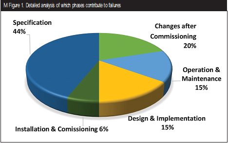
The main goal of functional safety is to prevent accidents. When people think of functional safety, keywords such as failure rates and safety integrity level (SIL), come to mind. However, these words only scratch the surface of understanding functional safety. Plant engineers and end-users know the use of IEC 61508 certified devices alone does not guarantee a safe design, especially with a final element assembly. For example, analyzed field failure reports for remote actuated valve assemblies show that the root cause for many of these failures is application mismatch, insufficient lifetime torque matching, and assembly errors. A study done in the UK supports this as well (Figure 1). The realization is that these automated valve assemblies do not always provide the anticipated safety.
Organizations and committees are now undertaking efforts to address these challenges and developing new recommended practices targeted specifically at remote actuated valve assemblies (RAVA). These practices increase the rigor associated with the enginee ring, design and testing of completed final element assemblies and have become the path forward.
Many manufacturers have started to adopt these new practices, which allow the complete assembly to be engineered, designed and tested as an integrated product. This added rigor has created a new form of functional safety certification with the potential to significantly reduce systematic failures resulting in a safer design and product.
SAFETY INSTRUMENTED FUNCTION ANALYSIS
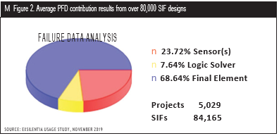
Statistical analysis of over 80,000 Safety Instrumented Function (SIF) designs shows that nearly 70% of the average probability of failure on demand (PFDavg) comes from the Final Element (Figure 2). The PFDavg metric represents the chance that the automatic protection will not work when needed. An objective of engineers who design these automatic protection systems is to lower the PFDavg as well as reduce the false trip rate. The false trip rate and PFDavg are based on several variables including the failure rate of all devices used for each SIF. These devices are classified into three groups: the sensor assembly, which detects a dangerous condition; the logic solver, which determines when to initiate the protection; and the final element, which does the protection work. The final element is often a remote actuated valve that opens or closes.
End users are looking for help from manufacturers to reduce this percent- age and make their plants safer.
CONTRIBUTING FACTORS
Numerous field failure reports show root cause due to inadequate lifetime torque matching, insufficient assembly testing, manufacturing errors or application mismatch. These automated valve assemblies do not always provide the anticipated and necessary safety. Often, the requirements for the final element are not specified with sufficient clarity and detail to facilitate a well-designed and verifiable subsystem. Combine this with the natural engineering process that focuses on getting things to work and rarely considers what happens when devices fail. A delivered RAVA is impacted by device manufacturers, distributors, engineering contractors, integrators, third-party suppliers, etc. Many opportunities for misunderstandings and design issues exist, and more needs to be done to apply the lifecycle engineering rigor required by IEC 61508 to the entire RAVA supply chain.
INDIVIDUAL PIECES VS. PRE-ENGINEERED FINAL ELEMENT ASSEMBLIES
Typically, a safety function design engineer will choose devices for a RAVA that meet process specifications. Often IEC 61508 certified devices will be chosen. Then the assembly is designed, and the devices are assembled by an integrator. How could this process be improved?
When a device (like an actuator or a valve) goes through a functional safety certification, numerous audit and assessment steps are done. One of the essential steps is an FMEA (failure modes and effects analysis) followed by a more detailed FMEDA (failure modes effects and diagnostic analysis). Each component failure mode is reviewed, then the impact on the entire device is identified and evaluated. This focus on what happens when failures occur identifies potential solutions to make devices better. The design engineering process is also carefully audited and must provide sufficient design analysis and testing. This is a proven method that is well established for the individual devices, however, can this approach work with a RAVA to provide verification and structure?
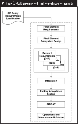
The answer is yes. The certification assessment approach works well on the entire RAVA (Figure 3). Several documents have been leveraged to obtain requirements for RAVA certification from organizations such as the Process Automation Users’ Association (WIB), International Organization for Standardization (ISO), Instrument Society of America (ISA), American Petroleum Institute (API) and American Society of Mechanical Engineers (ASME). The resulting requirements from these relevant standards/recommended practices define a certification scheme that will reduce engineering errors and omissions, characterize lifetime torque and match actuator output, provide complete design testing, and verify manufacturing quality. The program also requires a user document called a “safety manual” where safety design data, including application limitations, predicted failure rates, maintenance procedures and effective proof test procedures, are provided. The objective of the RAVA program is to achieve fewer false trips and higher safety by reducing engineering errors, reducing communication errors, finding and addressing problems in a design and reducing operational/maintenance complexity.
The RAVA certification scheme does not just ensure that the assembly was designed as a whole, but also includes a detailed review of the design parameters to accurately estimate design strength. When a manufacturer has innovative designs with special coatings, surface finishes and strong strength margins, credit is given. When an end-user application review is part of the assembly engineering process, the number of application mismatches is reduced, and credit is also given.
What does this really mean? Our chances of failure are getting increasingly smaller.
IMPACT ON SIF DESIGN VERIFICATION RESULTS
The RAVA products that have completed certification have shown low false trip rates and better safety resulting in a significant reduction in overall SIF lifecycle cost.
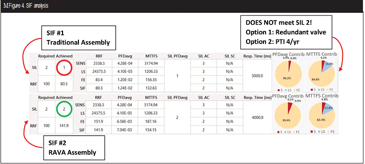
To demonstrate this, we utilized an engineering tool to perform a SIF analysis (Figure 4) containing a sensor, logic solver and final element assembly including a solenoid, actuator and valves attempting to achieve a SIL 2 SIF. Both SIFs have the same devices and assumptions have been maintained for both SIF #1 & SIF #2. The PFDavg contribution of the RAVA has been modeled for both SIF #1 (traditional assembly with individually certified devices) and SIF #2 (RAVA certified assembly). In this analysis we see SIF #1 achieves a SIL 1 level, which does not meet the target of SIL 2. SIF #2 RAVA achieves a SIL 2 level.
There are still two options that can be considered here to bring SIF #1 up to our SIL 2 target. In option #1, we can add an additional redundant Final Element assembly (making it a 1oo2 assembly). Or with option #2, we can decrease the proof test interval (PTI) to 3 months. Both of these options will add significant cost to both designing the SIF and its operational lifetime.
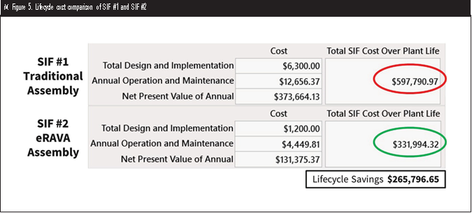
Evaluating the two SIF options in a lifecycle cost analysis tool (Figure 5) demonstrates a significant savings when using the SIF #2 RAVA certified final element assembly. In this example, a savings of 45% was achieved for an overall lifecycle cost reduction of $265,797.
SUMMARY
Even though devices used in remote actuated valves typically have IEC 61508 certification, it was recognized that more could be done. The IEC 61508 concepts could be applied to the entire assembly instead of only the pieces individually.
When considering the entire final element assembly, RAVA certification does just that. It is a credible assessment and certification process that can verify, validate and document improved remote actuated valve assemblies. Perhaps the result will be that remote actuated valves will no longer win the first place of safety reduction. And more importantly, end users will enjoy better products that significantly improve safety, reduce false trips and reduce overall lifecycle costs.
Loren Stewart, CFSE, is a senior safety engineer for exida. Along with assessing the safety of products and certifications, she is an exida Academy instructor and conducts monthly webinars on functional safety. Stewart is a published author on safety instrumented systems, Final Elements in Safety Instrumented Systems – IEC 61511 Compliant Systems and IEC 61508 Compliant Products.
Shawn Statham, CFSP, is the global business development director at exida. His career spans more than 25 years in the valve and automation industry. During this time, Statham has been an innovation leader in the field of functional safety, working to improve final element performance and reliability.
RELATED CONTENT
-
Electric Actuators in the Oil and Gas Industry
Actuators in the oil and gas industry operate many types of valves, and they must do so with great precision and accuracy.
-
Hardfacing Alloys and Processes for Advanced Ultra-Supercritical
Cobalt-based Stellite 6 has been the workhorse for providing improved wear resistance and service life in valve components installed in power generating facilities for over 75 years.
-
The Valve Industry Finds Value in ESG Initiatives
The valve manufacturing industry in North America is one of the industries that have embraced this new way of thinking and is leading the way with the integration of environmental, social, and governance (ESG) initiatives. These initiatives range from valves designed to mitigate climate change to community involvement activities.




 Unloading large gate valve.jpg;maxWidth=214)