What Makes Up a Servo Valve Feedback Mechanism is Mission Critical
To maximize machine operation and business results, engineers ought to consider more than how a servo valve performs with regard to flow/pressure gain, frequency response, and precision.
#pressure-relief
Quality Components Maximize Uptime
Selecting high-quality components keeps a machine operating, for longer periods. For example, test stands and full flight simulators are worth millions of dollars in revenue for their owners. If a servo valve or actuator in a test stand or flight simulator fails, the owners of these systems can suffer losses for delaying a product launch or training schedule that can exceed the purchase price of the stand or simulator.
It’s not uncommon for hydraulic servo valves to run for 25 years. But the engineers that recommend or buy these valves may not know why they perform for so long, even in demanding applications like steelmaking, test rigs, gas turbines and industrial production machinery.
Servo Valves Dictate Dynamic Performance and Precision
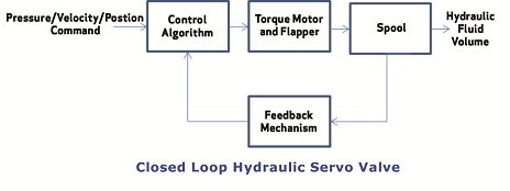
The servo valve is part of a closed-loop control system comprised of electromechanical mechanisms, and embedded software algorithms. And the electrical and mechanical design along with the material selection and manufacturing process ensures a servo valve performs as specified over its expected lifetime.
Closed-Loop Servo Valve Technology
Prior to 1951, hydraulic valves were primarily open-loop systems. The positioning of the spool was at best determined through empirical results in the laboratory under ideal conditions. When the feedback mechanism became part of the servo valve the accuracy of industrial machines was catapulted forward. The feedback mechanism precisely determines the position of the spool in the valve and stops the spool at a position proportional to the electrical input of the valve.
One nozzle-flapper design in a servo valve features a continuous flow of a small amount of fluid through two small nozzles facing each other. The pressure from the hydraulic fluid is directed to one side of a sliding valve referred to as the spool.
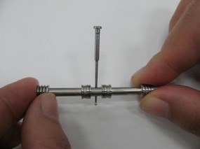
Servo valve makers precisely machine the spool to fit in a cylindrical chamber where it is displaced by the controlled variable-pressure hydraulic fluid. The feedback mechanism is a cantilever spring with a spherical ball bonded to the end. The ball contacts the spool in the chamber and is deflected as the spool moves transversally in the cylinder. The position displacement of the spool provides the position feedback for the servo valve control algorithm. The control algorithm in turn closes the position loop between the spool and valve flapper providing hydraulic equipment builders with precision control.
For the design engineer to assess that these performance specifications can be sustained throughout the life expectancy of the servo valve it is valuable to understand which components in the servo valve control loop are critical to early fatigue. When a servo valve’s internal components undergo early fatigue, they generally do not exhibit any external signs of degradation such as leakage. However, early fatigue affects the dynamic performance of the servo valve. Once the servo valve is mounted in the equipment, most equipment operators will not see any change in performance unless the system fails catastrophically.
Ball-in-Slot Design Marked First Generation
Carbide Replaces Stainless Steel
To overcome numerous sources of early wear in these components, designers turned to stainless steel for the ball on the feedback mechanism. By the mid-1990s, design engineers introduced the carbide ball. Carbide remains the material with the highest performance characteristics in the field. Engineers have also used a sapphire ball in servo valve technology, which is comparable to carbide for endurance.
Ball-in-Hole Technology Increases Life Expectancy
The manufacturing operation used to make the hole in the spool is referred to as “ballizing.” Ballizing creates a hardened surface in the spool that exceeds the capability of heat treatment. The surface area of the carbide ball in contact with the spool is increased to reduce concentrated contact at any one point on the surfaces. The “ball-in-hole” technology has now replaced the slot cut into the spool. Since 1998, the use of a carbide ball has remained state of the art.
Validating Ball-in-Hole Reliability
Despite the advantages of the ball-in-hole solution, there are products that continue to use the slotted spool configuration. To evaluate ball-in-hole versus ball-in-slot life expectancy, Moog tested both technologies.
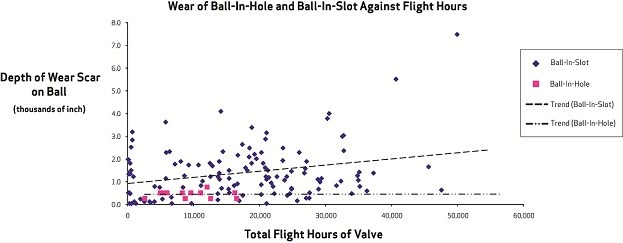
Test engineers assembled two servo valve models with steel balls; one model used a ball-in-slot configuration, the other a ball-in-hole. Engineers examined each valve for wear on the ball after running in the field for up to 50,000 service hours. Figure 7 plots the ball wear of both designs distributed across a range of 0.0 mils to 8.0 mils.
The wear on the ball-in-hole remained well below 1 mil for the duration of the test with a statistical variance near zero. In contrast, the ball-in-slot wear pattern had a wide statistical variance. The ball-in-slot configuration demonstrates wear patterns almost independent of service life including a number of instances of high wear below 1,000 hours of service. This suggests a difficulty in maintaining manufacturing tolerances. Further investigation showed wear in the ball-in-slot was the result of free rotation of the spool causing “adhesive wear.” The test results confirm that the ball-in-hole solution is far superior to the ball-in-slot design.
Techniques for Ensuring the Highest Reliability
There are other factors for design engineers to consider for increasing the reliability of the feedback mechanism. The feedback mechanism is composed of two pieces that must be attached in a manufacturing process; the mechanical feedback wire requires the mechanical characteristics of a stiff spring, and the ball requires hardness to minimize wear. There are two options for attaching the stainless steel wire to the carbide ball: (1) brazing and (2) epoxy.
Brazing
Brazing is a soldering technique joining two materials when the temperature exceeds (842° F/450° C). Technicians heat a filler metal above melting point and distribute it between two or more close-fitting parts by capillary action. The filler metal flows over the base metal, cools and joins the pieces. If the two pieces are free of contaminants and match up closely, while maintaining the proper temperature to melt the filler, the ball and wire joint will be stronger than the original materials.
Epoxy
Epoxy is an alternative to brazing. For example, sapphire cannot be brazed to stainless steel, so epoxy is used. Under perfect conditions the epoxy is an equally viable manufacturing technique. But, the chemicals in hydraulic fluids can deteriorate the epoxy even within normal operating temperatures from 0°F/-17.7°C to 160°F/71° C.
Therefore, design engineers should consider the manufacturing process of the feedback mechanism when evaluating a servo valve. Epoxy may equal brazing as a joining technique if machine operators fastidiously maintain the cleanliness of the hydraulic fluid. But epoxy’s susceptibility to temperature may be too much of a risk. In contrast, there are no known issues related to brazing stainless steel and a carbide ball.
Making a Mission-Critical Call
As design engineers consider the components for machines, they should give servo valve construction a closer look. The latest testing shows that carbide is as durable as sapphire. Research also indicates manufacturers can bond carbide to the feedback mechanism wire with a brazing process. Brazing enables the component to withstand hydraulic fluids and high temperatures, of course. And the ball-in-hole design extends the life of the servo valve by eliminating wear in the spool. Examining the details of servo valve design and making an educated choice can maximize uptime for your application and revenue for your business. And that’s mission-critical.
Daniel Baran is the Engineering Service Manager for the Mechanical Feedback Servo Valve Department at Moog. Baran has 10 years of experience designing and producing pneumatic equipment and 34 years of experience with hydraulics. He received his bachelor’s in mechanical engineering and master’s in business administration from the State University of New York at Buffalo. You may reach Daniel by writing to: bperry@march24media.com
RELATED CONTENT
-
Back to Basics: The Nuts and Bolts of Torque and Tension
Torque is a force that causes an object to rotate, while tension is a force that causes an object to stretch or elongate.
-
Proper Care of Knife Gate and Slurry Valves
How to resolve—and avoid—field failures of knife gate and slurry valves
-
Piping Codes and Valve Standards
As with every intended use for valves, piping carries its own set of standards that valve companies and users need to understand.


 Unloading large gate valve.jpg;maxWidth=214)

