The Rationale Behind Valve Characteristics
Back in the “early days,” we were taught that, to properly control flow, we should select a linear valve characteristic when the valve controls more than 25% of the piping system pressure drop at full flow.
#pressure-relief #controls #automation
Basics
A typical valve capacity term is Cv, which is defined as the number of gallons of 60⁰F (15.6⁰C) water that will flow through a valve with a pressure drop of 1 psi.
The inherent characteristic of a valve is demonstrated when a manufacturer measures flow volume and Cv value throughout the full range of valve travel.
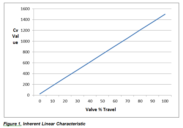
An inherently linear characteristic is defined in terms of what is shown in Figure 1, in which the valve Cv value changes in direct proportion to the valve travel.
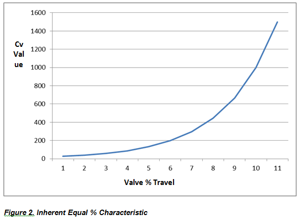
An equal percentage characteristic is when the valve Cv increases by a constant percentage over a given travel value. For example, the Cv may increase by 50% for every 10% increase in valve travel. In this case, if Cv at 20% travel is 100 and at 30%, it is 150, then at 40% it would be 225 and so forth, In other words, for every 10% increase in valve travel for this situation, the Cv increases 50% over the previous value (Figure 2).
Applying a Valve to a Flow Control Application
Taking all this into consideration, it would seem that if a party wants to control flow and also wants the flow volume to be proportional to the valve travel, that party would want to use an inherently linear valve characteristic. However, this assumption is wrong some of the time.
This is because, when we were discussing valve characteristics above, we were talking about the inherent characteristic that we’ve determined, not the installed characteristics. In service, a considerable portion of the system pressure differential will occur in places other than the valve—depending on the length of pipe, fittings and other equipment. As a valve opens and more flow passes through that valve and the piping system, the system consumes a greater and greater percentage of the entire system pressure differential. In fact, as flow increases through a length of pipe, the pressure differential across that length of pipe is equal to the square of the change in flow rate (i.e. two times flow equals four times pressure differential.)
To control flow then, the valve must have a rapidly increasing flow capacity, or in other words, it must have an inherently equal percentage characteristic so that the installed characteristic is more or less linear.
As an example, consider a valve installed in a plain pipe system with no components except the length of the pipe. Given a known valve Cv and a known pipe Cv, we can calculate the system pressure drop and the resulting flow volume throughout the full range of valve travel.
Other assumptions we’ll make to simplify this example are that the media is water at 60⁰F; there is a constant psig in the inlet head of 100; we have zero psig at the end of the pipe, the maximum valve Cv is 1,500 (which is Cv1 for this example); and we will compare three pipe lengths: 10 feet, constant pipe (Cv2 at 1,700); 100 feet, constant pipe (Cv2 at 530); and 1,000 feet, constant pipe (Cv2 at 167)
An analysis might look like this:
- We know valve Cv1; and we know pipe Cv2
- We can calculate the combined Cv value as Cvc = (Cv1 x Cv2) divided by (Cv1 + Cv2)
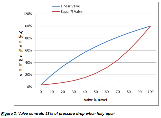
- If we increment the valve Cv1 from 0-100% using an inherently linear characteristic and also an inherently equal percentage characteristic, we can graphically show how the resulting flow rate varies based on the valve Cv1 value and the length of the pipe.
Following are examples that show the combined flow characteristic for linear and equal percentage valves installed in different systems.
Example: When pipe length is short (10 feet)—meaning the valve controls most of the pressure drop across the system—this occurs:
In this example, the inherently linear valve characteristic provides a nearly linear installed characteristic so it is likely the best choice for control of flow.
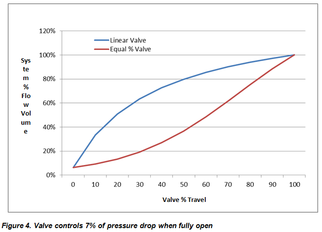
Example: When the pipe length is 100 feet, at maximum flow, the valve controls less of the pressure drop across the system so:
Here, the inherently equal percentage valve characteristic provides is nearly linear installed characteristic so it’s likely the best choice for control of flow.
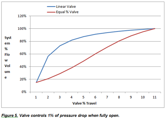
Example: When the pipe length is 1,000 feet, at maximum flow, the valve controls very little of the pressure drop across the system:
In this example, the inherently equal percentage valve characteristic provides a far better linear installed characteristic so it’s likely the best choice for control of flow.
As we see, when the valve employed has an inherently equal percentage characteristic, the longer the pipe (i.e. the non-valve system pressure differential), the more the system flow rate shows a linear characteristic.
Conclusion
As this shows, if the valve controls more than 25% of the full flow pressure drop (i.e. low pipe and system losses) a valve with an inherently linear characteristic to achieve system linearity should be used. If the valve controls less than 25% an inherently equal percentage characteristic would be best.
Of course numerous other valve characteristics exist but are not discussed here. The above information seeks only to demonstrate how to go about selecting the optimum inherent valve characteristic and where our early teachings on this issued derived. And here’s a final thought: Given today’s digital capabilities, one can use practically any valve characteristic and program to achieve system linearity.
Ed Holtgraver is founder, chairman and chief technical officer of QTRCO, Inc. (www.qtrco.com) in Tomball, TX. He is a former member of the VMA Board of Directors; a current member of VMA’s Education & Training Committee; and a recipient of VMA’s highest honor, the Person of the Year award. Reach him at ed@qtrco.com.
RELATED CONTENT
-
Back to Basics: Pressure Relief Devices, Part 2
In Part 1 of Pressure Relief Devices, which appears in VALVE Magazine’s Winter 2016 issue, the author stresses the vital role pressure relief devices play in keeping end-user industries that deal with pressurized equipment safe.
-
Operational Basics of Safety Valves
These spring-loaded valves provide overpressure protection for downstream equipment.
-
A Primer on Pressure Seal Valves
High pressure, high-temperature applications require a safe, leak-free pressure-containing boundary.




 Unloading large gate valve.jpg;maxWidth=214)