When Accessories Become Necessities
Specification sheets for selecting automated valves list requirements for the valve and actuator but often lump all other devices together as related instrumentation or accessories.
#actuators #components #controls
Since the definition of an automated valve is a flow control device that can be remotely operated, a typical selection hierarchy is:
- Select the best valve for the service conditions
- Select a suitable actuator to operate that valve
- Provide enough information on accessories so the valve supplier or end user can just add them as needed.
A comprehensive valve data sheet may enumerate 40 to 50 line items of information that define the scope of the valve assembly. Since performance and safety of that assembly are greatly impacted if any component in the assembly fails, the more forethought put into the specification, the more likely the final assembly will perform as intended. The purpose of a specification is not to exclude any manufacturer but rather to include only those products the specifier perceives as most closely meeting the equipment application requirements.
THE SPEC SHEET
If we look at all system devices as necessities instead of accessories, we can divide the specification sheet into three sections.
- Under Process Components all devices that are in contact with the media would be listed. That would include the valve and instrumentation such as flow meters and other process variable transmitters.
- Under Force all devices that supply the motive power to operate the valve would be listed. This would include the actuator—pneumatic, electric or hydraulic; hand-wheel overrides; linkage kits/mounting brackets; solenoid valves; filter regulators; pressure gauges, etc.
- The third column would be headed Intelligence. This category would include valve position sensors. Intelligent devices interface the operator’s commands and the valve’s response. Without supervision/control, the automated valve will not function; therefore, the process will not function.
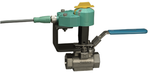
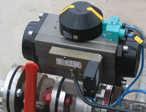
An inductive proximity sensor is a non-contact device, which means the sensor is free from wear. A common metal target is mechanically attached to the actuator stem of a linear or rotary travel valve. When the target comes into range of detecting the sensor, an electronic switch changes state, which confirms the position of the valve. Actuation speed or frequency has no effect on inductive proximity sensors. They are typically used in pairs, one for the valve’s open position and another for the closed position, although sensing other positions can be easily accomplished. Dual sensors directly mounted onto a pneumatic actuator provide valve open and valve closed switching in one compact package. Proximity sensors are available in a variety of configurations and voltages and can be an integral part of a valve assembly, especially when the sensor’s full capabilities are utilized.
MORE THAN A SWITCH
Proximity sensors are more than solid-state switches. They are also intelligent communication devices that can be wired directly to a programmable logic controller’s (PLC) input card or a node on a network such as AS-Interface. These sensors are the watchdogs of the valve assembly, continuously providing the status of the valve’s position. When valve movement is initiated by the control system operating the process, the sensor indicates the actual valve position. When the controller instructs the valve to move, the valve position sensor confirms the valve has reached the desired position. Without a sensor, all that’s known is that a command was given, not that it was executed. Most proximity sensors are discrete devices, though some provide a continuous analog output as well.
AS-Interface networks can communicate easily with controllers manufactured by many different companies and with other networks including DeviceNet, PROFIBUS, Modbus and Ethernet.
Many direct-mount valve position sensors can also power the coil of a solenoid valve, which simplifies the electrical wiring. On rotary actuators, the target (or puck), serves as a beacon, visually indicating valve position. Integral light-emitting diodes that show switching state and power provide local indication and are useful during commissioning. A separate National Electrical Manufacturers Association (NEMA)-rated enclosure to house the sensors is often not needed, although sensors are frequently mounted in switchboxes where specified. Inductive proximity sensors also have high switching frequencies.
A mechanical limit switch has a spring-loaded actuating arm that makes physical contact with a cam or roller rotated or moved by the valve’s actuator stem. When the arm is compressed by the cam, metal contacts touch, completing an electrical circuit. Periodic adjustment of the actuating cams is often required, while readjustment of an inductive proximity sensor is required only rarely.
Mechanical switches are also prone to failure from metal fatigue, corrosion or self-welding. Rapid actuation also can cause contact bounce, which appears as signal echoes in the PLC.
Reed switches are mechanical switches actuated by a magnetic target. While they are non-contact devices, they generally have slower switching frequencies than inductive proximity sensors. Reed switches are also prone to trip in high-vibration environments and when strong magnetic fields are present such as in an industrial application.
Two-wire NAMUR-rated inductive proximity sensors provide a solution for sensing and switching in hazardous environments. A NAMUR-voltage and current-limited sensor mounted to a valve assembly that resides in a hazardous area (such as an explosive or potentially explosive environment) is wired to a switch-isolating barrier located in a safe environment. Proper application of safety-rated sensors that have appropriate cables and barriers can even eliminate the need for metal enclosures and expensive conduit runs. Yet they can provide system safety up to Safety Integrity Level 3.
A valve assembly specification must include all the electrical and communication parameters the valve position sensor must meet. Sensors are available in 2-wire and 3-wire DC as well as AC and AC/DC versions. Some are also programmable, and various electrical connections are available.
LOOKING AT THE WHOLE SYSTEM
The accuracy and dependability of instruments is essential. As with any selection situation, several ways to perform a function can be used. While many products will do the job today, intelligent products will allow a better job and the ability to communicate now and in the future with modern plant control systems.
Equipping manually operated or automated valves with position sensors will provide the process operator additional important system information. A manually operated valve in the wrong position cannot be detected without a sensor. Also, by using sensors, no one must go into a location to check valve position that’s in a hazardous or difficult to reach area. Instead, the sensor can do the job.
David Fink is key account manager, Process Equipment, Pepperl+Fuchs. Reach him at dfink@us.pepperl-fuchs.com.
RELATED CONTENT
-
Electric Actuators in the Oil and Gas Industry
Actuators in the oil and gas industry operate many types of valves, and they must do so with great precision and accuracy.
-
Linear Actuators for Automating Gate Valves
Most professionals in the valve industry are already familiar with the use of linear actuators to operate globe valves.
-
Erosive Pulp & Paper Systems Require Proper Valve Selection
As new recycled paper plants are being built for the first time in decades, not only do paper companies have opportunities to grow revenue but so do service suppliers such as valve companies.


 Unloading large gate valve.jpg;maxWidth=214)