
Produced by


Published January 11, 2022
Sand erosion in control and choke valves is a significant consideration offshore.
By Adrian Croft, Control Valve Product Manager, Trillium Flow Technologies
Sand erosion in control and choke valves is a significant consideration offshore. Sand can cause erosion to both the valve trim and the pressure envelope. Nothing can withstand sand erosion, but thoughtful valve and trim selection can increase the life of the valve and trim and maximize the time between maintenance intervals.
Although sand can occur in a number of systems offshore, most of the issues surrounding sand erosion can be expected around the wellhead or the separator system.
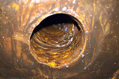
Example of sand collection on the underside of a valve bonnet.
A modulating control or choke valve manages the pressure drop by controlling the area through the trim. The closer the plug is to the seat, the more the trim area is restricted and, therefore, the higher the velocity of the fluid across the trim. Ultimately, the higher the velocity of the fluid with sand present, the quicker the erosion. When sand is present, the slower, the better.
The velocity of a fluid through a valve can simply be reduced by maximizing the flow passages. Larger-sized valves with large bores are often preferred but are more expensive. The pressure drop and the fluid velocity should be jointly considered to select the most appropriate valve size.
Where sand is present, the optimum valve body style is an angle valve as it will pass the solids into the downstream pipe with minimum impingement onto the body walls.
In some cases, it is not possible to use an angle valve, and globe valves are specified. The flow should always be over the valve plug when using a globe valve. This will eliminate direct impingement onto the body wall. Additional protection can be provided by a seat diffuser, which prevents direct impingement of the fluid onto the bottom of the globe once pressure reduction has taken place across the trim.
Single-stage cage designs are ideal for contaminated duties. First of all, they are low-pressure recovery designs, and secondly, they have a simplified flow path.
The fluid passes from outside to in, meaning that the fluid jets impinge together in the center of the cage, ultimately ensuring that energy is reduced with minimum contact to metallic surfaces.
Where possible, multi-stage trims with 90-degree turns should be avoided in contaminated duties as sand is likely to become trapped in a 90-degree bend. Depending on the quantity of the sand, the valve can quickly become blocked.
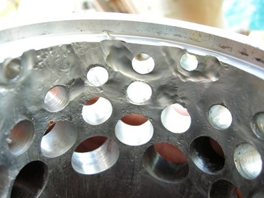
Sand erosion across a metallic cage
Where a multi-stage trim is required, severe service valves are often specified. Care should be taken when selecting these trims because most designs rely on the process being turned around 90-degree bends. Care should be taken to select a multi-stage trim specifically designed to handle solids, which will allow debris, such as sand, to pass through the trim without blockage. Trims designed where the entry flow path is larger than the outlet flow path should be discouraged as they are likely to block up. Instead, trims that feature the smallest openings at the fluid entrance should be used.
As discussed, sand causes erosion by impingement on material surfaces. Therefore, it follows that if the material surfaces are harder, then the rate of erosion will be reduced. Tungsten carbide is generally used in this situation due to its relative hardness. Solid tungsten carbide inserts are shrunk into the cage, plug and seat in the areas with the maximum potential for erosion. Solid tungsten carbide can be used but could be subject to cracking due to compressive loads in the valve.
In some cases, ceramic materials can be used, but most specifications call for tungsten carbide in the oil and gas industry.
The one significant disadvantage with tungsten carbide is that it is very brittle. Imagine it like a tile in a bathroom, very resistant to wear, but if dropped, it would shatter. There is, therefore, an advantage in holding the carbide in steel housing. In the cage, the steel outer cage also acts as a “brick stopper,” so if there is any large debris in the pipe, the steel cage will protect against impact damage.
Tungsten carbide must be carefully designed to prevent stress points that can ultimately lead to stress cracking and failure of the carbide section.
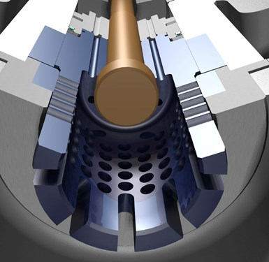
Typical choke valve with a tungsten carbide trim
When using tungsten carbide, cavitation must be eliminated. Cavitation eats away at the binder holding the carbide particles together. It also generates shock cells and can lead to vibration. Due to the carbide being so brittle, cavitation can lead to catastrophic component failure.
Severe service trims, primarily based on disc stack technology, can be manufactured in solid tungsten carbide. However, some design considerations have to be taken into account; for example, the discs need to be approximately six to 10 mm thick. This is due to the properties of the carbide in the manufacturing process. If the discs were thinner, they would be likely to crack. In the majority of cases, a tungsten carbide disc stack would have to be unitized (glued) together for additional strength.
Conventional valve trims have an angled seating point so that when the valve is seated, the plug and seat are in contact. On contaminated duties, fluid impingement can lead to erosion of the seating face and leakage across the trim. To minimize direct fluid impingement, a protected seat can be applied. The protected seat has a lip around the valve plug. This means that the fluid does not directly impinge on the seating surface.
Additionally, the protected seat also ensures that there is a deadband so that when the plug lifts, the valve has to open further out of the seat pocket to expose the first set of holes in the cage. This additional lift means there is a reduction in velocity across the seating face.
Sand erosion and particle tracking are possible using modern Computational Fluid Dynamics (CFD) techniques. These can be used to simulate the flow patterns in the valve and then track the sand particles through the flow domain.
Prediction of Sand Erosion in Process and Pipe Components by Det Norske Veritas, Proc. 1st North American Conference on Multiphase Technology, Banff, Canada 1998, gives an equation for the erosion rate in a given small sub-area, found by the summation over all particles that hit within that defined area. This methodology can be used to predict the life of trim components. For example, a customer was concerned about the safety condition of a valve during a gas blowby case and wanted a flow limiter installed in the valve. The flow limiter’s erosion rate was then calculated to determine service intervals.
There are many challenges offshore, but controlling sand and particulate erosion ensures the longevity of components and ultimately means costly interventions are reduced to a minimum, ensuring maximum oil and gas production.
Adrian Croft has worked in the control valve industry for more than 44 years. He has had roles in control valve engineering design, parametric design programming, applications engineering and smart instrumentation technology. Adrian’s current role of control valve product manager for Trillium Flow Technologies has a wide-ranging scope and often leads to front line involvement in process industries, including power, oil and gas, LNG and petrochemicals.


June 26, 2026
Why engineered mounting kits are critical to valve automation integrity.
April 7, 2026
Simple automations can create big gains on the shop floor.
April 3, 2026
