Evaluating and Proving SIS Safety Levels
Because the equipment used in a safety instrumented system (SIS) application has a critical job, such equipment must be carefully evaluated and justified.
#automation
Evaluation and justification includes two areas of analysis:
Application Match
Any piece of equipment chosen for safety applications must match functional and environmental needs. Actuator/valve assemblies, for example, must be looked at for seat tightness and closing times. In addition, the materials used in all equipment for a SIS must be compatible with process materials, a reality that is especially important in wetted services typically found in the oil and gas and chemical industries. Process environmental conditions must not exceed ratings, and application evaluation is common sense, and therefore, common practice. A newer area of evaluation and justification is safety integrity justification.
The functional safety of equipment also must be assessed as to whether the equipment is safe enough for specified safety integrity levels. Justification decisions in this area must be documented as part of project records.
Rigorous safety integrity justification has been a common practice for sensors and programmable logic controllers, but only recently has such attention been given to solenoid valves, actuators and valves used in the SIS final element.
So how can an engineer assess the functional safety of an actuator or a valve? IEC 61511, Functional Safety for the Process Industries, requires that equipment used in safety instrumented systems be assessed based on either IEC 61508 certification or an evaluation the standard calls “prior use.” Unfortunately, the standard does not give specific details as to what constitutes the criteria for prior use. Most agree, however, that if a user company has many years of documented successful experience (i.e., no dangerous failures) with a particular version of a device, this provides a good foundation for prior use justification. Most also agree that prior use justification requires vendor quality audits and that a comprehensive system should be in place to record field failures and failure modes at each end-user site.
Records of the different versions of equipment must be kept because design changes may void prior-use experience. Operational conditions must be recorded and must be similar to the proposed safety application.
However, a problem with prior-use approaches is that many process sites simply do not have those levels of recordkeeping in place.
Because of this, many users have asked their manufacturers to help with this particular justification.
Help From Manufacturers
A manufacturer can provide two aspects of justification: 1) Failure rate and failure mode data for each piece of equipment; and 2) The manufacturer’s design process and manufacturing process quality audit.
Failure Rate and Failure Mode Data
Failure rate data is important so that system designers can create safety function designs adequate for process risk reduction requirements. Several techniques are used to predict field failure performance, including cycle test data; manufacturer’s warranty return data; and failure modes effects and diagnostics analysis (FMEDA).
- Cycle test data: Cycle testing is a method used primarily on mechanical equipment to determine wear-out mechanisms. The method also is used to predict the random failure rate during the useful life of a device.
The testing method assumes premature wear-out from a manufacturing defect would be the dominant failure mechanism and that no other failure mechanisms would be significant. This assumption is valid in common mechanical applications with frequent motion.
A specified quantity of devices are cycled until they fail 10% of the time (10% fail). A calculation is done based on a cycle rate for a given application to determine the failure rate.
Because cycle testing assumes constant dynamic operation, it is used for high-demand applications only, not for static or low demand. This means the method is rarely valid or used for safety instrumented system applications that might remain dormant for long periods of time. Cycle test failure rates should only be used for safety functions with frequent demand rates (demands of at least once a week).
- Manufacturer’s warranty return data: This data can be used to approximate predictive field failure rates on new products. It depends on a number of assumptions. However, often the assumptions used result in publication of highly optimistic failure rates. The most optimistic assumption may be that all field failures are reported. A survey of end users found that often it is less expensive to throw away a product than to send it back to the manufacturer. Also, sometimes repairs are made by the end users, and the failure is not reported back to the manufacturer. This is especially true of mechanical devices such as valves and actuators for which rebuild kits are offered. Overall end-user survey results indicated that roughly 10% of failed items were actually sent back to the manufacturer. This number is higher during the warranty period; but some users reported that 0% were sent back after the warranty period.
Another issue with this type of data analysis is return categorization. As products are returned, they are tested. Many times these tests show “no problem found.” It is assumed those returns must not be real failures so they are not counted.
A second optimistic assumption is that such tests can detect all possible failures. But what if the failure occurs only under specific field conditions not duplicated in the manufacturing test? What if the test simply is not complete and does not detect all failures? Many returns are classified as “not a problem” or “customer abuse.” All of this depends on the manufacturer’s warranty policies, but frequently, real failures are not counted.
- FMEDA: The hardware analysis called FMEDA can be done to determine the failure rates and failure modes for a piece of equipment. An FMEDA is a systematic detailed procedure first developed for electronic devices and then extended to mechanical and electro-mechanical devices. Each part in a design is given a failure rate based on field failure data. The failure modes of that part are examined to determine the failure mode of the device.
Failure rates are added for each mode. Some assessors also do a useful life analysis to provide safety instrumentation engineers with any wear-out mechanisms and the time periods until they wear out. Some FMEDA analysis is also extended to evaluate the effectiveness of given proof test coverage factors including partial valve stroke testing. The information can be used for more realistic probability of failure on demand average calculations.
One of the major advantages of the FMEDA approach is that component failure rates can be established for different operating environments. The failure rates of certain mechanical components used in valves (e.g., solenoid valves) and actuators vary substantially depending on operation. Seals such as O-rings, for example, have fundamentally different failure modes when used in applications with frequent movement (dynamic) versus applications with infrequent movement (static). When both sets of failure rates are established, FMEDAs can provide data sets for both static and dynamic applications, or in high and low demand.
Manufacturer Design and Production Audit
In addition to good failure rate and failure mode data, a manufacturer can provide third-party audit results for its design manufacturing processes.
The manufacturing process audit has been going on for some time and is often covered thoroughly by an ISO 9000 style audit. The design process audit report is not as common, but some manufacturers can supply a report that can be used by an end user as evidence in a prior-use justification.
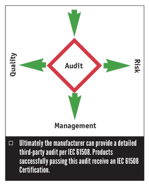
A trend among manufacturers is for them to provide a certificate and a full assessment report according to the requirements of IEC 61508. The full assessment should include an FMEDA, as well as a detailed assessment of the design and manufacturing processes. An IEC 61508 assessment digs deeply into the methods used for new product development and also provides detailed study of the testing, modification and user documentation.
Many of the requirements of IEC 61508 focus on eliminating systematic faults through use of the world’s best product design methods. To demonstrate compliance with all requirements of IEC 61508, a product creation process must show extensive use of many fault control and fault avoidance procedures. These methods and procedures must be applied with different levels of rigor when they are a function of the safety integrity level (SIL) rating of a product. When a product has demonstrated full compliance with the requirements of IEC 61508, the end-user has a high level of confidence that the product will provide the level of safety specified in its SIL level rating.
Conclusion
All of these assessment techniques, including the full IEC 61508 certification, do not evaluate the suitability of a device for a particular function. End users must specify and evaluate any product for their particular installations.
As safety instrumented systems are designed and implemented, it is clear that manufacturers and end users must work together to achieve optimal functional safety. The manufacturer must specify the environmental and application limitations. The end user must design the product into an application that will not exceed the limitations of the instrument design.
In addition, field reliability and safety performance must be communicated to the manufacturer so that any unanticipated design issues are understood and communicated to all end users.
Loren Stewart is a safety engineer at Exida (www.exida.com). Reach her at L.Stewart@exida.com.
RELATED CONTENT
-
The Final Control Element: Controlling Energy Transformation
When selecting control valves, be sure to properly evaluate the process conditions to identify potential issues and select the proper management techniques.
-
The Future of Valve Manufacturing is Already Here
Companies in the valve and control products industry are responding to a confluence of forces that are changing the landscape of manufacturing — automation, agility and digitalization to name a few.
-
Additive Manufacturing of Pressure Equipment
How manufacturers can design and produce PED-compliant equipment using additive manufacturing.


 Unloading large gate valve.jpg;maxWidth=214)