
Produced by


Published April 6, 2022
The application of control and choke valves used in offshore oil and gas production is a very broad field and in this article, some of the main considerations for valve selection will be addressed.
By Adrian Croft, Control Valve Product Manager, Trillium Flow Technologies
When selecting a valve, the first consideration is: Which standards should be applied? These standards range from international and country standards, engineer-procure-construct (EPC) organization’s standards and client
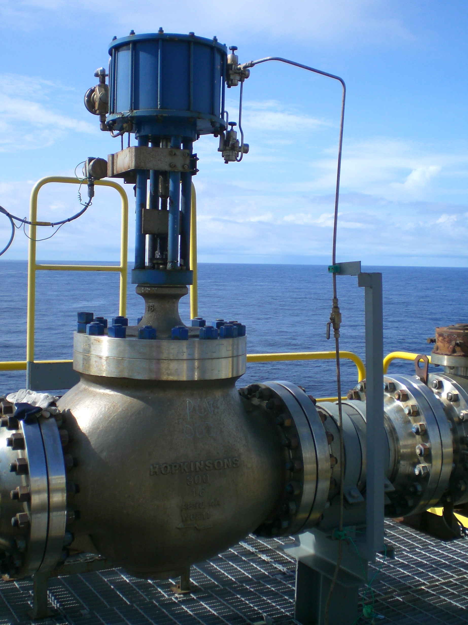
Typical valve installed offshore. Photo credit: Trillium Flow Technologies
specifications. Often, standards will conflict in some details, so determining the priority or discussing priorities with the user is important at the onset of the project. For example, most EPCs have established their own painting and coating systems. In some cases, an EPC will state that a paint system must be applied to all external components, even if they are manufactured from corrosion-resistant alloys. Others simply specify that exposed components (such as nuts and bolts) should be 316 stainless steels. Selecting valves in the offshore industry, therefore, relies on the experience of the manufacturer’s sales engineer to both size the valve according to the specifications, but also to select the valve and correctly interpret the requirements of the specification.
The major systems fall into the following categories; however, it should be noted that some processing might be done onshore, well chemistry might dictate that some of these systems are not required. Equally, additional systems might be required for additional processing. Each system, depending on the oil and gas pressure, fluid type, etc. will dictate the valve requirements. Systems can be broadly categorized as follows:
Additional systems, not directly part of the production process are:
The one big consideration for offshore is to determine if the fluid contains sand. If there is sand in the process fluid, then trim and body protection need to be carefully considered. In clean applications, trim selection is largely a function of pressure drop, noise and velocity; however, when sand is present, this poses an additional challenge in selecting a trim to reduce the rate of erosion, while not blocking up with sand. Much of the selection comes from experience and knowing the application and process and being able to address the issues during the specification of the valve.
In the majority of processing systems downstream of the separators, the gas will be clean. Historically, much of the gas produced was a by-product of the oil and much more was flared off than today. These days, both due to environmental concerns and due to the value of gas, gas that is not re-injected is mostly shipped to market. There are many techniques for exporting the gas that largely depend on the location of the rig or vessel, but invariably, compressor and anti-surge systems will be required to pressurize the gas. In valve terms, clean gas is not an erosion concern. There are, however, issues with noise, velocity and vibration around these valves and the system. It is important that the valve supplier is advised of the correct process conditions, and if associated with the compressor, be made aware of the selection rules. For example, compressor suppliers often have a requirement that the valves should be 50% open at the normal flow condition.
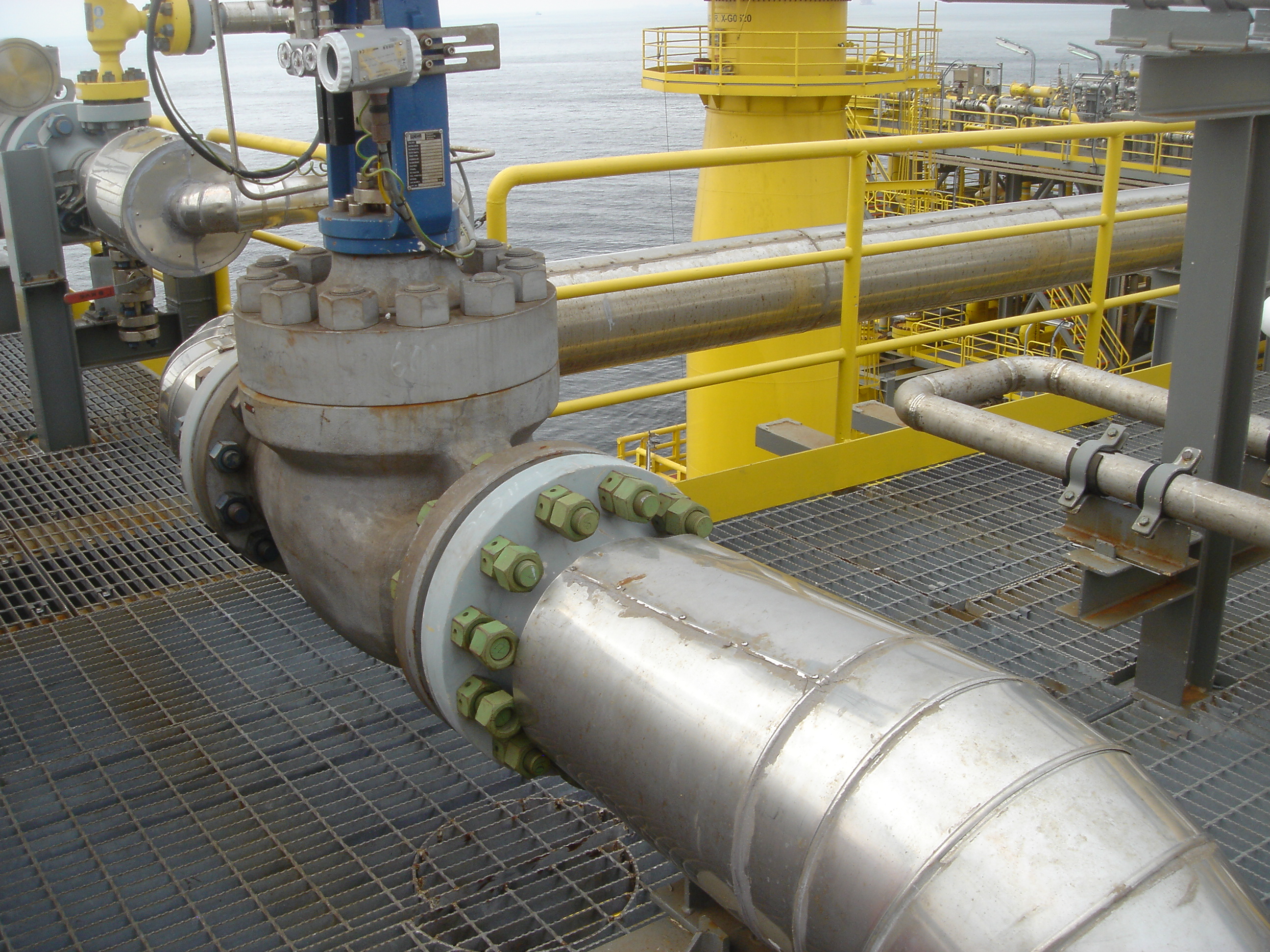
Typical valve offshore situated close to bends. Photo credit: Trillium Flow Technologies
Space is limited due to the physical constraints of the rig or vessel. Ultimately, the space limitations mean that the valves are often located close to 90-degree bends, which, in turn, can generate fluid stability issues and ultimately pipework vibration. Control and choke valves are best located in straight pipe runs with a minimum of five straight pipe diameters upstream and downstream (longer runs in some applications). In the majority of cases, the valve supplier will not be made aware of the pipework restrictions and the locations of bends. However, if there is thought to be an issue, then the valve supplier can often increase the number of pressure reduction stages in the valve to help to stabilize the flow. Overall, it is easier to make enhancements to the valve at the onset of the project rather than being forced into pipework modifications during commissioning.
Although valves are only one component in a piping system, the weight of the equipment to be installed offshore is a major consideration as the support structure or vessel must be designed to hold the weight of the processing systems. On larger, high-pressure valves, significant weight savings can be made by considering the valve specification and design. For example, if we consider a 12-in. flanged Class 2500 rated valve, the flange weight might be approaching one ton. Switching from an ASME flange to either a “compact flange” or hub connection could offer both a weight and cost saving, especially where more expensive materials, such as duplex, are used.
Valve materials should be carefully considered. In the majority of applications, cast valves can be used. However, utilizing forgings should be considered where material integrity, such as on the choke valve, is important. Around the well head, valves are mostly designed to API standards, then downstream systems such as separation are designed to ASME. It is possible to use both cast and forged materials according to the API standard, but the standard dictates the minimum material strength. According to the product specification level (PSL), forged valves can either be fabricated by welding. On higher specifications, welding is completely excluded. On larger valves, where stamped forgings are not available, then alternative body manufacturing techniques can be considered. For example, HIPping large bodies in exotic materials can offer a cost-effective solution for the manufacturer.
In NACE applications where high-value corrosion-resistant alloys (CRA) are required, an alternative could be to use a carbon steel valve with an Inconel internal overlay applied to the wetted surfaces.
When applying ASME materials according to ASME B16.34 design standards, the customer mostly specifies the pipe materials and therefore the applicable valve material. However, again, careful material selection can sometimes result in cost savings; for example, instead of selecting a WCB valve body, a WCC body offers a higher strength material at the same cost and therefore in some cases the valve pressure rating can sometimes be reduced.
When considering the actuator, most actuators are specified as pneumatic diaphragm or pneumatic piston. These actuators, being air operated, are relatively safe in a hazardous environment. The actuators are mostly manufactured from carbon steel that is coated with a suitable paint for an offshore environment. Historically, most of the actuator yokes would be manufactured from cast iron, but a number of specifications now call for carbon steel yokes. On their standard actuators, many suppliers would use 304 stainless steel on exposed components such as bolting, stem coupling and stem. This is not suitable for an offshore environment, as it still corrodes. As a minimum, all exposed actuator components should be manufactured from 316 stainless steel.
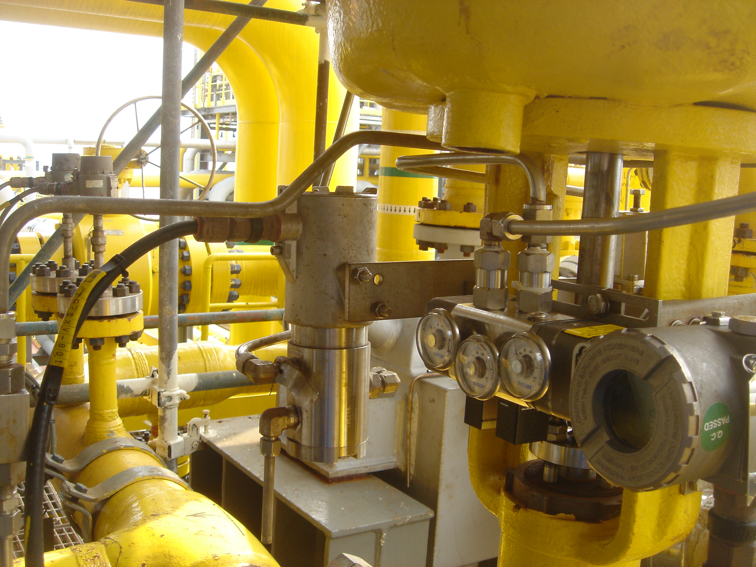
Stainless steel instruments installed offshore. Photo credit: Trillium Flow Technologies
Other actuator designs such as manual, electric or electro-hydraulic can also be used offshore. The selection of these methods of actuation is mostly application specific and will be determined in the customer specification. Manual actuators are mostly specified on valves that will be operated infrequently, for example, around the flare system when manual intervention is required. The use of electric actuators is not common offshore, but when selected on specific projects they offer good control and are “stiff,” meaning that once in position, process instabilities will not affect the actuator position. Normally offshore there will be a hydraulic ring main that will provide full hydraulic power to electro-hydraulic actuators. When compared to other industries, valves with electro-hydraulic actuators are relatively simple. Electro-hydraulic actuators are often specified in applications where high thrusts and stable control are required. They are also often used on unmanned platforms.
Instruments used in an offshore environment have evolved to address specific issues encountered offshore. Although the selection of instruments is a wide-ranging topic, most instruments such as airsets and solenoids were available in 316 stainless steel. It is only in the past 20 to 30 years that valve positioners have been available in 316 stainless steel. Prior to that, positioners were generally supplied in a painted aluminum. It was mostly found that painting failed due to chipping of the paint which led to corrosion of the aluminum. In the majority of cases due to these inherent issues, valve instruments are now virtually all specified in 316 stainless steel.
There is no doubt that the oil and gas industry has been at the forefront of the development of painting and coating techniques for salt-laden environments; however, no matter how good the painting and coating system is as the valve leaves the factory, it is only as good as the people who install and maintain the valve during operation. Often during installation or maintenance, paint becomes chipped, which in turn means that the atmospheric barrier is broken, which can lead to failure of the valve or actuator.
Each valve supplied will automatically have a hydro and seat leakage test performed on the control or choke valve. However, these days legislation, standards, company specifications mean that additional testing is typically required on the valves. This can range from material testing or product qualification test/specification such as safety integrity level (SIL), through to specific production tests, such as gas testing, fire testing and fugitive emission testing. As user specifications are often derived from standards, we find that the standards have been incorrectly applied or misinterpreted, especially through EPCs, so that ultimately customers are asking us to test valves when it is not required. A common example (especially in the Middle East) is that fire testing is often specified on control and choke valves. When it is explained to the EPC that the standard only generally applies to isolation valves (such as ball or gate valves), then the requirement is often waived.
Valves in the oil and gas market will always be required to push the boundaries of what is possible. As water depths become deeper, the fluid pressure is increasing and, in control and choke valve terms, becoming more severe. If we consider choke valves, 10 or 20 years ago, 10k choke valves were considered high-pressure valves, but these days they are now mostly standard and valves of 15k and higher are often used in new installations. Ultimately, it is a case of having a dialogue with the customer to both understand the process and produce the best valve solution for the application.
Adrian Croft has worked in the control valve industry for more than 44 years. He has had roles in control valve engineering design, parametric design programming, applications engineering and smart instrumentation technology. Adrian's current role of control valve product manager for Trillium Flow Technologies has a wide-ranging scope and often leads to front line involvement in process industries, including power, oil and gas, LNG and petrochemicals.


Why engineered mounting kits are critical to valve automation integrity.
April 7, 2026
Simple automations can create big gains on the shop floor.
April 3, 2026
Prevention can help operators avoid system damage and shutdowns.
March 30, 2026
