The Industrial Revolution of the late 1800s brought about widespread use of steam as a means of generating power, performing work and delivering heat to industrial process systems. While an effective and efficient means of providing heat and power, steam use brought several challenges, one of which is the effective removal of condensate to ensure thermal efficiency and prevent mechanical damage inside of piping, turbines and process equipment.
To meet this challenge, the steam trap was born. Today, as in its early days, the steam trap is the device primarily responsible for automatic discharge of condensate from steam systems. Effective use of these traps can ensure that maximum thermal efficiency is maintained at the same time that mechanical damage to equipment is avoided. Ineffective use of steam traps, however, can lead to accidents, reduced process capabilities and significant energy losses throughout a plant.
Steam traps are automatic valves that differentiate between steam and condensate. Their primary function is to discharge condensate from collection points in distribution piping and process equipment, and then close tightly on steam to prevent unnecessary energy loss. As the steam space in most systems is full of air at ambient temperatures, a secondary function is to vent air during startup.
STEAM TRAP APPLICATIONS
Steam trap applications can be understood best by dividing them into three broad categories: distribution drainage, forced heat process and steam tracing. By understanding the operating characteristics of each of these applications, proper steam trap selection and sizing can be performed.
Distribution Drainage
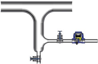
For saturated systems, steam will always be condensing as it flows through the piping, resulting in condensate collecting at low points in the system. These low points must be drained to prevent condensate from building up and eventually joining the steam flow, which would cause waterhammer, a very dangerous condition resulting from condensate traveling at high velocities within a steam system. Waterhammer occurs when the high-density water meets a restriction in the piping—such as a control valve, an elbow or tee—creating violent pressure shocks. Many of the accidents involving steam systems result from piping or valve failure due to waterhammer. Effective drainage of distribution lines will ensure that only dry steam reaches critical points.
Distribution drains require steam traps to vent large amounts of air at startup, discharging high initial condensate loads resulting because steam piping is at ambient temperatures followed by low, hot-running condensate loads. After startup, steam pressures tend to be stable until a system shuts down.
Forced Heat Process
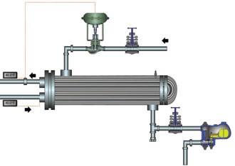
Forced heat process applications require steam traps with large air-venting capacity, the ability to handle fluctuating condensate loads and the ability to handle fluctuating differential steam pressures.
Steam Tracing
Most steam tracing applications require low-condensate capacity at relatively stable saturated steam pressures. However, steam tracing on high-temperature process piping can result in superheated steam being produced and reaching the trap, a factor that should be taken into account when selecting the proper steam trap.
TYPES OF STEAM TRAPS
Steam traps manufactured today fall into three major categories based on operating principles: mechanical, thermostatic and thermodynamic. These operating principles tend to determine the applications for which the steam trap is most appropriate.
Mechanical Steam Traps
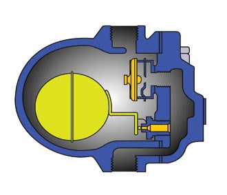
Float steam traps consist of a cast iron or steel body containing a sealed float connected to a valve mechanism. When condensate enters the trap body, the float becomes buoyant, opening the valve and releasing the condensate to the discharge side of the trap. When all condensate has been drained and the trap body fills with steam, the float keeps the outlet valve closed, preventing the loss of live steam. Since the float mechanism responds in the same way to air as it does to steam, by keeping the valve closed, a separate thermostatic element is often added to the steam trap to control the discharge of non-condensable gases. These thermostatic elements consist of either liquid-filled bellows or bimetallic plates. With the addition of such elements, the trap becomes a float & thermostatic (F&T).
F&T steam traps are most appropriate for low-pressure distribution drainage applications as well as forced heat process applications at low to medium pressure. By discharging condensate at steam temperatures, these devices ensure efficient drainage of process equipment. However, the thermostatic element tends to make them susceptible to damage by superheated steam as well as waterhammer. F&T traps can fail in both the open and closed position. Failure in the closed position can lead to significant damage to process equipment from freezing.
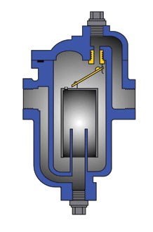
Inverted bucket traps can be installed on both distribution drainage and forced heat process applications. These devices discharge condensate at steam temperature, making them well suited to draining process equipment. However, the limited air-venting capacity requires that a secondary air vent be installed in parallel on equipment that has large air-venting requirements or frequent start-up and shut-down cycles. Inverted bucket traps should not be installed on superheated steam applications because the excess heat will cause the internal water prime to be lost, resulting in the frequent and premature failure of these valves.
Thermostatic steam traps
Thermostatic steam traps operate through a temperature difference between steam and condensate. While steam and condensate can exist at the same saturated temperature, the thermostatic trap takes advantage of the tendency of condensate to rapidly lose temperature when it collects in dead legs off of the main flow path of the steam line.
Bellows traps tend to be suitable for low- to medium-pressure distribution drains and tracing. They can only withstand a small amount of superheat in the steam. Failure can be in either the open or closed position.
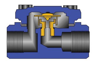
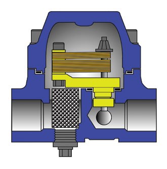
Bimetallic designs are suitable for distribution drainage and steam tracing at low, medium and high pressures. The inherent durability of bimetallic plates make them ideal for superheated steam applications as well as use on saturated systems where waterhammer may occur. Although sub-cooling requirements vary from one bimetallic design to another, bimetallic steam traps are not generally thought to be the best choice on forced heat process applications where condensate discharge at steam temperature is required. Because the valve resides on the downstream side of the orifice, bimetallic steam traps incorporate a built-in check valve and tend to fail in the open position.
By discharging condensate at temperatures below that of steam, thermostatic steam traps typically maintain higher operational efficiencies than steam traps of other designs.
Thermodynamic steam traps
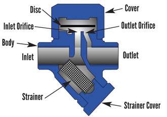
Upon startup, the differential pressure across the trap pushes the disc off the seating surfaces and flow begins. When the condensate is evacuated from the system, steam flows through the trap, increasing the flow velocity (Figure 10), creating a low-pressure area below the disc, pulling it onto the seating surface. As the disc seats, the greater surface area of the disc stops the flow.
The steam trapped above the disc keeps the disc seated (Figure 11). As radiant heat loss from the cover and body of the TD trap causes the steam trapped above the disc to condense, the disc lifts off of the seat and flow commences, causing the cycle of discharge and shutoff to continue (Figure 12).
TD traps are widely used on distribution drains and steam tracing for low-, medium- and high-pressure systems. Their compact size and relatively low price point make them attractive to plants that have large populations of steam traps. Failure mode of the TD trap is in the open position.
ENERGY CONSIDERATIONS
As with all mechanical equipment, steam traps are subject to wear and failure at any point in their life cycle. However, steam traps present a much larger potential to produce energy losses than many other types of valves. Many steam traps fail in the open position, resulting in large and unrecoverable losses of steam. Consider that a steam trap with a quarter-inch orifice installed on a 100 psig system can lose up to $15,000 per year if not repaired. This can be a very expensive prospect in most plants where steam trap populations can sometimes number in the tens of thousands. Also, failure rates can typically reach 10% annually, underscoring the need for a comprehensive testing and repair program for traps. Many companies provide steam trap testing and diagnostic services. Facilities that do not currently conduct an annual steam trap audit or have a testing and repair program, should contact their steam trap vendors, who can point in the right direction for getting trap failures under control.
CONCLUSION
The commercial landscape of steam traps around the world is populated with many choices. Because of the varied requirements of different applications in industrial plants, regional preferences, or sales and marketing history, plant engineers today are faced with a wealth of options for meeting their condensate drainage challenges. The success or failure to choose the right steam trap depends on the ability of the design-maker, who must meet the requirements of specific applications and match those requirements to the capabilities of different steam trap technologies.
TERRY ACERS is vice president of the James D. Acers Company, a master distributor for Velan Steam Traps. Reach him at tacers@ velansteamtraps.com.
RELATED CONTENT
-
Fundamental Operation of Pilot-Operated Safety Relief Valves
In this second of a series, we explore another type of pressure relief valves used in common applications.
-
Pressure Relief Valve Basics – Spring-Loaded Safety Relief Valves
Learn for the first time or brush up on this common valve product.
-
Direct-Sealing Diaphragm Valves Offer Novel Approach
As modern industries such as hydrogen electrolysis and biotech make dramatic technical advances, engineers and researchers must sometimes turn to nontraditional process control systems.






 Unloading large gate valve.jpg;maxWidth=214)