The Noble Globe Valve
The most common type of valve in the world today is probably the globe valve.
#basics #gate-globe-check
Yet the globe is also the valve of preference in virtually all industries in which flow rates need to be regulated. The basic globe valve is also similar to its more complicated cousin, the multi-turn control valve. In fact, the control valve is really just a globe valve with bells and whistles attached in the form of automatic control, balanced operation, positioner, controller, feedback circuits and more.
Although the globe valve can be used as a block or isolation valve, it is primarily designed to regulate flow in the partially open position, while gate valves are designed for either the fully opened or fully closed position. When considering globe valves for on-off isolation service, design selection should receive careful consideration because maintaining a tight seal against the strong force pushing up on the disc is difficult.
Piping designers, when specifying a valve, primarily consider how well it emulates a straight run of pipe while in the open position. Valves such as the gate, butterfly and full-port ball types do a very good job in this respect. However, the globe valve, because of its convoluted interior flow path, does not do well at imitating a straight pipe run. Instead, the angled zigzag flow creates fluid friction, which in turn slows down the fluid flow through the valve. The “Cv” (or the flow rate coefficient measurement) for the same size gate and globe valves will be vastly different, since the gate valve offers little flow resistance while in the open position.
The globe valve closure mechanism, which is called a disc or plug, can be machined into many different shapes. By changing the shape of the disc, the rate of flow through the valve as it opens can be varied greatly in proportion to the number of turns of the stem. Most services use the more common or “conventional” ball or spherical-type disc design because it opens more than other designs for any given movement of the stem. The V-port disc design is used for fine throttling through a wide range of opening percentages and is adaptable to all sizes of globe valves. The needle disc design is used for very fine flow regulation, but usually only for smaller sizes. When absolute shutoff is required or when there is a problem sealing fluids with minute suspended particles, a soft-seating elastomer insert can be installed in either the disc or the seat.
THE TRIM
In globe valves, the components that bear the brunt of the fluid flow during the closure operation are called trim. They are the seat and disc facing, stem and sometimes the hardware that connects the stem to the disc. Correct trim design and proper selection of trim materials are critical for maximum operation and longevity of any valve, especially globe valves, which have high fluid friction and convoluted flow path. As the seat and disc move closer together, the velocity and turbulence across both increases, creating potential for damage by cavitation and erosion. This elevated velocity can cause the trim to be eaten away, resulting in a valve that leaks badly in the closed position. When a globe valve is used to control highly corrosive fluids, the damage from cavitation and erosion may be compounded. Sometimes this defect looks like a thin slice in either the seat or disc, which is called wire-drawing. However, if not promptly repaired, this initial small leak path can widen and become a major leak path.
On smaller bronze globe valves, the trim is either the same material as the rest of the valve or a similar bronze alloy with greater strength. On iron globe valves, the usual trim material is bronze. The designation for this trim on iron valves is “IBBM”, which stands for “iron body, bronze mounted.” Steel valves are offered in a variety of trim materials, but usually have one or more of the trim components of 400 series martensitic stainless steel. Hard facings such as Stellite are also used, as well as 300 series stainless steels and copper-nickel alloys.
PATTERNS AND DESIGNS
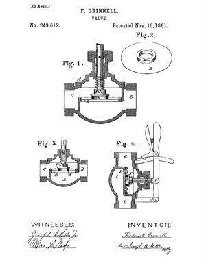
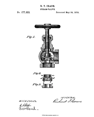
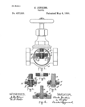
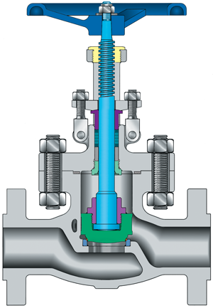
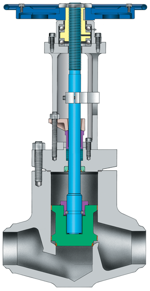
Globe valves are available in three basic patterns. The most common is the “T” pattern, where the stem is perpendicular to the pipe line. Similar to the T pattern is the angle pattern, but the flow is turned 90 degrees in the valve to allow the angle valve to serve as both a flow control device and 90-degree piping ell. The angle pattern globe valve is still commonly used on top of boilers and is the pattern used for most chokes on oil well production units, called Christmas trees.
Valve designers have not been content with basic globe valve design. While other older valve designs such as the gate and plug types have stayed pretty much the same as 100 years ago, designers have stretched the limits of the globe valve to make it into a high-performance flow control device.
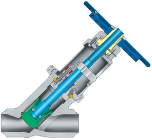
The third and newest design, the “Y” pattern, was developed in an effort to reduce the turbulence that takes place in the body of a globe valve as well as provide a more rigid design. In this type of globe, the bonnet, stem and disc are slanted at 30 degrees to 45 degrees, resulting in a straighter flow path and less fluid friction. This reduced friction means less potential for erosive damage to the valve, as well as better overall flow characteristics for the piping system.
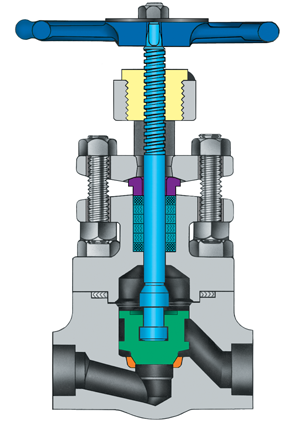
Globe valves come in a variety of bonnet designs, and each design has its own purpose. For small bronze valves, the inside-screw-rising-stem design is the most popular. In this design, the stem threads are contained within the pressure/fluid envelope of the valve bonnet. Such a design is easy to manufacture, but it does have one drawback—the threads are exposed to the process fluid. As a result, the critical stem threads can be damaged when exposed to corrosive fluid. However, this type of valve is normally used for water or low-pressure steam.
On valves larger than about NPS 2 or for valves in corrosive service, bonnet designs—where the stem threads are outside the pressure/fluid envelope—are much preferred. The most common of these designs is called the outside screw and yoke, also known as OS&Y, which is the most common design for larger industrial globe valves.
The body/bonnet connection on globe valves comes in a variety of designs. Both threaded connections and union bonnets are found on the smaller bronze valves, while the bolted bonnet is found on most steel and iron globe valves. The pressure seal bonnet is used on high-pressure, high-temperature globe valves, such as those with the Y pattern design.
THE BOILER CONNECTION
Globe valves and boilers have literally and figuratively been connected for more than 150 years. In fact, globe valves are so critical for boilers that the American Society of Mechanical Engineers (ASME) Boiler and Pressure Vessel Code dictates how the valves should be used in boiler service. The first valve on a boiler output line is usually a stop-check valve, also known as a non-return or boiler stop valve. The stop-check is actually two valves in one—a globe valve for regulating flow and a check valve for preventing backflow. The disc on a stop-check is not attached to the stem but is guided in the valve bonnet—allowed to freely move up and down when the stem is raised. This allows regulation of the flow rate, but when backflow occurs, the disconnected disc functions as a piston check valve and quickly closes, preventing reverse flow into the boiler. If required for tighter shutoff, the stop-check stem can be lowered, preventing movement of the disc to the full open position.
In addition to regulating boiler output, the stop-check valve is also used for other applications where combining a check valve and globe valve makes sense for the piping designer.
Another boiler globe valve application traces its heritage back to the iron horse. When you see pictures of a locomotive with huge plumes of steam streaming from its sides, you are looking at a boiler blow-down globe valve at work. The blow-down valve allows the removal of excess water from a boiler that is occasionally required. Blow-down globe valves are still in use on stationary boilers.
AN ADAPTABLE DESIGN
The globe valve not only kick-started the valve industry as a whole but also created the huge control valve segment that exists today. Control system designers took the original globe valve and morphed it into an automatic regulating device to solve fluid control issues in a more productive manner. Initially these pressure-regulating globe valves were developed to control steam in boilers and pumps. These early regulating valves, also known as governors, are now called control valves and are used worldwide in virtually every industry requiring fluid control.
The design of globe valves also is very adaptable to services other than regulating or blocking a handwheel or actuator. If you take a standard globe valve, remove its handwheel and yoke bushing and replace those with a calibrated spring or counterweight, the globe becomes a pressure relief valve. If you remove that same handwheel and yoke bushing and replace them with a float and lever, it becomes a level control valve. And probably the most visible globe valve adaptation is the fire hydrant, which is a globe valve with the handwheel and yoke bushing replaced by a long extension tube and a fireplug hat.
SMALLER IS BETTER
Unlike some of the other valve designs such as the gate and butterfly, the globe is not commonly manufactured in very large sizes. This is partly because the large area of the disc acting directly upon the stem creates a much greater force than what is created for a gate or other on-off valve of the same size. Larger globe valves operating at high-differential pressures almost always require some mechanical assistance to close under pressure, usually in the form of a manual or motorized gear operator, or in some cases, a hammer-blow handwheel. Due to the large surface area of the valve disc and the pressure exerted on the disc from below, large, low-pressure globe valves require additional strength in bonnet designs to keep them from flexing and leaking past the seats while in the closed position.
While very large globe valves are not common, small globe valves that fit in the palm of your hand are. These small valves, usually manufactured from solid barstock, are used extensively for instrument valves in scientific environments, fluid sampling applications, or anywhere that small-diameter, fluid regulation is required. Many are needle-disc types and provide very precise flow control. Some are also fitted with various tubing connections to allow easy connection to tubing lines. While most globe valve stems are of the rotating type, some have non-rotating stems to lessen the possibility of stem galling.
The majority of globe valves are designed for regulating flow, but some specially designed, high-pressure, Y-pattern types are adept at tightly sealing fluid flow in block or on-off service. Because the disc moves down directly on the seat, the thrust on the stem is transferred directly into the seating force. This allows virtually all the actuator output force to be used for sealing the valve against leakage. Most often, these high-pressure globes are built with pressure-seal instead of bolted bonnets. The pressure-seal bonnet increases its sealability as the internal fluid pressure increases.
Globe valves typically have a preferred flow direction, which is usually confirmed by an arrow stamped or cast into the outside of the valve body. For most general plumbing and industrial applications, the primary flow direction is upward against the disc. This upward flow is smoother on and around the disc, and it provides free rotation of the disc on the stem, which allows the valve to find its proper seat or “fit” when closing. In some applications, such as high-pressure-blocking or on-off service, the preferred direction of flow is down onto the top of the disc rather than under it. But these situations are rare.
STANDARDS AND MATERIALS
Globe valve design and construction is covered under a number of industry specifications. Strangely enough, the American Petroleum Institute (API), which has standards for all other major valve types, has no standard for globe valves larger than NPS 2. Table 1 lists some of the more common standards for globe valves.
Materials used in globe valve construction run the gamut from basic bronze to high-nickel super-alloys. Bronze is still the most-used globe valve material, followed closely by iron and cast steel. For cryogenic applications, stainless-steel and bronze globe valves are popular, requiring only an extended bonnet to keep the packing gland area from freezing.
Table 1. Common globe valve standards
MSS SP-42 — Class 150, corrosion-resistant, gate, globe and check valves
MSS SP-80 — Bronze gate, globe, angle and check valves
MSS SP-85 — Gray iron globe and angle valves, flanged and threaded ends
MSS SP-118 — Compact steel globe and check valves (chemical and petroleum refinery service)
API 602 — Steel gate, globe and check valves for sizes dn 100 (NPS 2) and smaller for the petroleum and natural gas industry
BSI 1873 — Steel globe and globe stop and check valves (flanged and butt-welding ends) for the petroleum, petrochemical and allied industries
ISO 12149 — Bolted-bonnet steel globe valves for general-purpose applications
MSS – Manufacturer’s Standardization Society of the Valve & Fitting Industry
API – American Petroleum Institute
BSI – British Standards Institute
ISO – International Standards Organization
Whether it’s controlling bath water in a faucet, oil in a refinery or steam in a power-plant, globe valves “soldier on” 24 hours a day. Even though their basic design hasn’t changed much in 150 years, these noble members of the valve family continue to work well and should provide valuable service to the flow control industry for the next 150 years.
Greg Johnson, a contributing editor to Valve Magazine, is president of United Valve (www.unitedvalve.com), a valve service facility located in Houston, TX. Johnson is a member of the VMA Communications Committee and is chairman of VMA’s Education & Training Committee. Reach him at greg1950@unitedvalve.com.
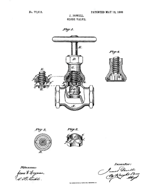
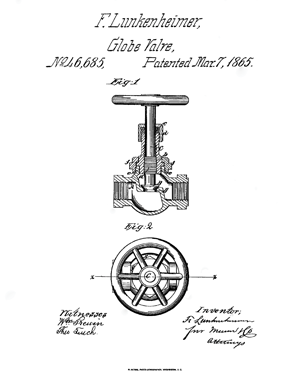
THE GLOBE VALVE STARTED IT ALL
That says many things, but primarily it tells us the product that put the “valve” in valve industry was the humble globe valve. Designed originally to regulate steam in the 1800s at the astonishing pressure of about 150 psi, these valves were mass produced long before Henry Ford, the father of mass production, was born. After 150-plus years the basic internal design of the globe valve has changed little, and they are still being built and sold by the thousands every year
RELATED CONTENT
-
Ball Valve Basics
Welcome to the first in a series of Valve Basics articles, each focused on a major product type and written especially for newcomers to the industries that use and make valves and related products.
-
Selecting Non-metal Materials for Valve Components and Coatings
Non-metallic materials are commonly used for valve components, and the selection of non-metallic materials for valve design and for application-specific conditions is critical to ensuring product reliability.
-
Water Hammer
Water hammer is a shock wave transmitted through fluid contained in a piping system.




 Unloading large gate valve.jpg;maxWidth=214)