The Valve Industry’s Role in Climate Change
The world may not agree on all the causes of climate change, but most people realize our actions over the last 150 years have directly contributed to greenhouse gas (GHG) buildup, most notably accumulation of carbon dioxide and methane.
#VMAnews #water-wastewater
Energy balance equations clearly reveal that the result is increased global temperatures and higher sea levels over this century.1 The debate continues about how severe the planet’s situation is, but science tells us we better take notice and take action soon.
Although the valve industry’s role is not often recognized, the industry can be critical in mitigating climate change. This occurs through education of valve users on how to reduce energy consumption and how to control emissions through valve selection, advanced valve technology and modern factory management. While governments around the world contemplate various treaties and policies, the valve industry actively participates in solutions.
ENERGY SAVINGS
Valves are vital to most fluid systems because they control and contain flow and pressure, release gases, and prevent backflow and leakage. Their ability to minimize energy consumption, thereby reducing carbon footprint, is often overlooked.
Pumping systems need significant energy to overcome the combination of the static head of the system and the friction head of the piping. The friction head is caused by roughness of the pipe’s inside surface as well as local flow disturbances from fittings and valves. Although valves come in many varieties, they cause friction head in similar ways.
Valve body geometry dictates the general flow area through the valve. A common practice is for valves to restrict the flow area to below 80% of the pipe area. Also, the internal contours of the body and seat may be rough or contain cavities and transitions, which creates excessive turbulence. The design of the closure member is important for two reasons: First, the lowest head loss is achieved if the closure member swings or rotates out of the flow path. Second, the closure member for check valves should have contours that mean they fully open at low fluid velocities and create a smooth flow path through the valve.
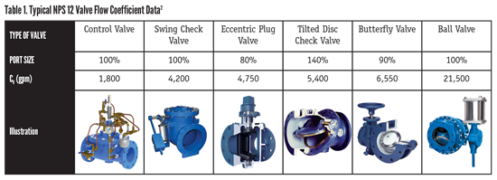
Computing the head loss produced by various types of valves is normally simple—the most ubiquitous flow coefficient for valves is the Cv flow coefficient, which is defined as the amount of water (in gallons per minute or gpm) that will pass through a valve with a 1 psi pressure drop. Hence, the more efficient the valve, the greater the Cv. Table 1 presents the flow characteristic and generic Cv values for several general valve types showing that the full port ball valve has the highest Cv given its full, unobstructed flow path.
To save energy, it is important to consider the head loss between types of valves; the head loss between various suppliers of a given valve type does not typically produce significant changes in system operations. This fact is also the reason piping system computer simulations accurately model system behavior based on generic valve characteristics data.
The flow conditions of the system also can affect the valve head loss. In general, head loss is a function of fluid velocity squared. That means a doubling of the line velocity will increase the pipe, fitting and valve head losses four-fold. This is why pump discharge velocities are typically held to the 8- to 16-foot-per-second range, and pipeline velocities are kept to the 4- to 8-foot-per-second range. Since valve coefficients and head loss are a function of velocity, the overall cost of energy consumption versus pipe costs should be evaluated to see where there is an optimum pipe size and velocity that provides the lowest present value of installation costs plus annual operating costs.
Water and wastewater plants in the United States annually consume about 75 billion kilowatt hours (kW-hr) of energy.3 Nearly 80% of the energy is consumed by potable water plants for high-service pumping to overcome the static head and friction losses of distribution systems. Water utilities have an opportunity to employ various energy saving strategies, including valve selection, that can result in a 20-50% reduction in energy consumption, thereby reducing operating costs.
The head loss from valves can be directly converted into an energy cost related to electrical power needed for the pumping to overcome the additional head loss from the valve, using this equation4:
A = (1.65 Q ∆H Sg C U) / E
Where:
A = annual energy cost, dollars per year
Q = flow rate, gallons per minute
∆H = head loss, feet of water
Sg = specific gravity, dimensionless (water = 1.0)
C = cost of electricity, $/kW-hr
U = usage, percent x 100 (1.0 equals 24 hours per day)
E = efficiency of pump and motor set (0.80 typical)
An example for a Nominal Pipe Size (NPS) 12 control valve operating at 12.7 feet per second would be:
A = (1.65 x 4500 x 14.42 x 1 x .08 x 0.5) / 0.8
= $5355 per year
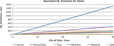
Moreover, saving electrical energy reduces the need for burning fossil fuels, which further reduces ways to create GHGs. On a national average, for every kW-hr of electricity used, about 1.14 pounds of CO2 emissions are generated. This means in the example above the use of a ball valve instead of the control valve could result in savings of 1,525 tons of CO2 emissions over the 40-year life of the system (Figure 1).
AIR RELEASE
Another family of valves important to energy conservation are air valves. Even after a pipeline is commissioned, air is continually introduced into pipelines from vertical pumps, entrained air and external connections. It often comes as a surprise to pipeline designers that the cause of a pumping system’s inefficiency or stoppage can be a result of air in a pipeline because many people assume it is easier to pump air than water.
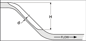
When several highpoints in a pipeline exist, the head losses are additive. Therefore, during initial pump startup, the line can appear to be blocked because the pump cannot overcome the sum of the head losses in all of the highpoints—even at the pump shutoff pressure.
Using automatic air valves eliminates the air pocket and restores the pumping efficiency of the pipeline.
VALVE TECHNOLOGY
Not that many years ago natural gas valve actuators may have been powered by the process fluid, which consists mostly of methane. The pressurized gas was used to drive a valve actuator cylinder and then was expelled to the atmosphere. This was before GHGs were monitored and their impact fully understood. Today, we know that certain GHGs such as methane have 25 times the impact on the greenhouse effect as others such as carbon dioxide. As a result, process valves are now powered by clean gases or fluids.
Another cause of emissions is leakage through valve stem packing. The valve industry worked with the American Petroleum Institute (API) to develop valve packing and valve testing standards to verify that valves meet emission requirements the U.S. Environmental Protection Agency (EPA) has established. API standards now follow EPA low-emission requirements of 100 parts per million (ppm) for five years and provide testing and qualification steps for valve packing and valve assemblies at various mechanical and thermal cycles. While no valve is perfect, the valve industry is prepared to meet the requirements set for fugitive emissions to reduce effects on the environment.
Finally, recent improvements in ball valve technology have allowed greater energy conservation. New materials and manufacturing processes mean ball valve seating systems have advanced greatly over the last decade. Both metal seats and resilient seating technology have been reengineered to provide low- to zero- leakage under extreme conditions. The advent of five-axis computer numeric coding machining capabilities means ball valve manufacturers can now make perfectly matching spherical ball and seat-metalized surfaces. As a result, a ball valve can be used for traditional high-temperature globe valve applications in power plants, which saves energy and reduces GHGs from the ball valve’s extremely high Cv.6
Evolving valve technology also contributes to new energy technologies. A global emphasis has been placed on new energy generation systems to mitigate climate change, including renewable energy sources such as biomass, hydroelectricity, geothermal power and nuclear power. Valve technology is following that development to support these evolving energy technologies. For example, the safe, high-performance nuclear valves available for decades are now used with new, passive nuclear plant designs and high-temperature recycling reactor waste systems to make nuclear energy generation an attractive solution.
VALVE FACTORIES
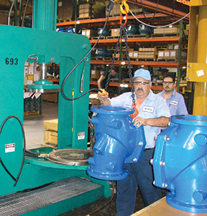
U.S. valve manufacturers and other industries take social responsibility seriously and actively engage in activities that mitigate climate change. Examples include using energy-efficient lighting and equipment in factories. Meanwhile, coating processes for valves have migrated from solvent-based coatings to coatings with high solids content to reduce volatile organic compounds. More advanced coatings include powder-based coatings with zero emissions such as fusion bonded epoxy (FBE).
An important focus in the valve industry is lean manufacturing practices. Lean manufacturing is not about cutting jobs, but rather improving processes to reduce waste. Many tools are employed to accomplish these goals, but all of them are designed to improve the efficiency of the overall manufacturing process.
Conclusion
Valves not only play an important role in the function of piping systems, they also can reduce energy consumption and help mitigate the release of greenhouse gases. For example, proper selection and placement of air release valves can greatly enhance the energy efficiency of fluid systems. While it is important for purposes of efficiency to calculate the head loss and energy costs associated with valves, these energy savings also translate into a reduction in the world’s carbon footprint. The valve industry has evolved rapidly with new technologies and products to help in these efforts, and it will continue to find ways to contribute to the mitigation of climate change.
John V. Ballun, president and CEO of Val-Matic Valve, is a regular contributor to VALVE Magazine. Reach him at jvb@valmatic.com.
REFERENCES
- IPCC, 2013: Climate Change 2013: The Physical Science Basis. Contribution of Working Group I to the Fifth Assessment Report of the Intergovernmental Panel on Climate Change, Cambridge University Press, New York, NY, USA, 1535 pp.
- Val-Matic Valve, “Energy Cost Calculator,” www.valmatic.com/ecalc/calc.php.
- Oliver, Julia and Cynthia Putman, “How to Avoid Taking a Bath on Energy Costs,” OPFLOW, Vol 23, No. 5. May, 1997.
- AWWA M49. 2001. “Butterfly Valves: Torque, Head Loss, and Cavitation Analysis,” 1st edition, Denver, Colo.
- Edmunds, Robert C. “Air Binding in Pipes,” Journal AWWA, Vol 71, No.5, May, 1979.
- Spilker, Steve, “Ball Valves in Power Plants,” VALVE Magazine, Winter, 2012, pp. 27-34.
- Ballun, John, “Taking the Heat,” Water Wastes Digest, September, 2015. pp. 10-11.
RELATED CONTENT
-
Five Reasons Why the Right Strategy Leads to the Success of Digital Transformation Implementation
The past few years have proven that digital transformation (DT) is more than just a trend. It is becoming one of the frontrunners for ensuring business continuity through modernizing times. However, despite being an essential component for adaptability in a competitive industry, not all companies would consider their DT implementation a success.
-
Misconceptions Regarding Control and Isolation Valve Standards
All on/off isolation valve standards are not created equal and cannot be applied unilaterally to all valves.
-
DBB and DIB: Which is which?
The term “double block-and-bleed (DBB)” carries a lot of misconception when it’s used to describe valve functionality.




 Unloading large gate valve.jpg;maxWidth=214)