Those Dam Valves and the Great Job They Do
As the nation increasingly seeks sources for renewable energy, dams and the thousands of valves they contain will only become more important.
To get an idea of the valving used in dams, we need to look at how dams work. Although we tend to think of them as structures designed to hold back water and create attractive recreational lakes, their true purpose is much more complicated. Dams are usually built to provide crucial water resources, and in more and more cases, their purpose is to provide renewable electrical energy.
All dams of substantial size need to have a way of releasing water in controlled amounts because of changing reservoir capacities, downstream water demands or minimum stream flow requirements. These situations call for special valves designed to dissipate the large amount of energy created by the high head of water in the dam.
WHAT VALVES ARE USED
At first glance, it might appear that virtually any type of shutoff valve would work, but a closer look at the operating conditions provides a broader picture. These outlet valves, which are releasing water, are doing so at huge volumes, relatively high head pressures and at a resulting high velocity. The combination of output flow conditions can result in severe damage from cavitation at the valve outlet. This phenomenon can rapidly destroy many types of valves, so measures to abate the cavitation must be taken either in valve selection or piping design.
The needle valves, however, have done a good job for many decades, yet newer designs have now replaced many of those work horses. Both fixed-cone and jet-flow gate valve designs are now used in such applications and are currently being retrofit into existing structures as funds permit.
The fixed-cone, or Howell-Bunger valve, is a simple balanced design that requires little energy to open or close. The outlet of a fixed-cone valve is very similar to the outlet of a fireman’s hose nozzle or a high-end home garden hose nozzle, in that the high water pressure is squeezed around the periphery of the stationary cone by changing the position of the circular seat that is inset in the inside diameter of the moveable sleeve. The flow is regulated by adjusting the amount of water pressure introduced into the chamber behind the cone via a regulated water inlet.
The jet-flow gate valve looks like a large fabricated slab gate valve, similar to some API 6D designs. However, the secret to its energy-dissipating success is in the flow chamber of the valve. As designed, the slightly smaller inlet, with an inward taper just before the gate area, directs the mass of water into a narrow jet as the water exits the valve. The downstream port of the valve also flares out to avoid damage from the intense jet of water.
This design eliminates the possibility of cavitation damage. However, if the valve has a submerged outlet, a “stilling chamber” needs to be provided to dissipate the turbulent water flow and prevent scouring damage. A stilling chamber is a large pool of water sized to dissipate the output water energy without damage to the surrounding underwater landscape. If the jet-flow gate valve releases into the air, a structure-free zone needs to be provided for the length of the outlet stream.
Hoover Dam replaced all 16 of its first generation 84-inch and 96-inch needle-type regulating valves and their companion cast “Paradox emergency gate valves” in 1998 because of safety concerns. The Paradox block valves were in line upstream of each needle valve to allow for the maintenance of the complex needle valves when required. All those valves were replaced with fabricated jet-flow valves.
Some reservoirs may use a form of globe valve located in a valve house in a deep part of the lake near the dam. These inlet structures offer a path for water to pass through the dam differently than over its top or through sluice gates. In the simplest of dams, this may be only a passive intake pipe open to the top to allow water over a certain depth to bypass the dam and flow through piping to the other side of the dam structure.
While the valves in a simple reservoir-only dam may be rudimentary, the valving in a large hydroelectric dam can be extensive and unique because of how the water flows through the dam and through turbines to create electricity.
THE ELECTRICITY FACTOR
So how does the water in a dammed up lake generate electricity? The answer lies in the potential energy that the deep and heavy volume of water creates. When piped through a tube into a generator turbine, this great weight or mass of water will act to move the turbine blades, which causes them to rotate rapidly. A common shaft to a generator connects to the rotating turbine blades and creates the electricity.
In modern hydroelectric dams, the water input lines or penstocks to these turbines are often very large, sometimes up to 15 feet or more in diameter. The larger volume of water in feet per second means that a larger generator can be rotated, and thus more electricity can be generated.
These butterfly valves can be massive, and in many cases, they are built into the body of the dam. Therefore, complete replacement is cost prohibitive. This means they have to be designed so that they can be repaired in place.
One of the oldest and probably still the largest butterfly valve installation in the United States is in Exelon’s Conowingo Dam in Pennsylvania. The huge, 27-foot, port-size butterfly valves are big enough for a two-lane highway to pass through them. These valves have been operating since the dam opened in 1927 and are still in use today, providing a means of dewatering the turbines if repairs or upgrades are needed.
Although not huge by Conowingo standards, the butterfly valves in Hoover Dam are also impressive. They were designed and patented by the United States Bureau of Reclamation (USBR) in 1934. There are 16 156-inch butterfly valves, each one isolating a power-generating turbine.
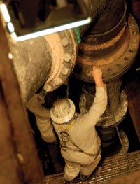
To provide an idea of their size, each requires a 12-inch bypass line. These unique monsters are built into the dam so their removal in case of repair would be almost impossible. Their existence has created opportunity for the ultimate valve repair field service.
THE LITTLER GUYS
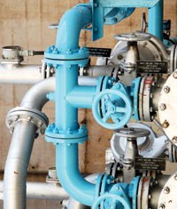
Besides the dinosaur-like giant dam valves, there are many less exotic types found in the inner workings of a large hydroelectric dam. The turbine feed lines often have parallel connections to other turbines in case a turbine must be fed from another source. There are also utility lines, often up to 36 inches in diameter, that allow water to be diverted to different inputs or outlets as the need arises.
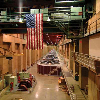
A walk in the subterranean vaults of a dam such as Hoover reveals a myriad of pipes and valves, not unlike a walk through a large steam power plant or refinery. One nuance of these installations is that there is no wasted space. Everything is stacked together with no extra room, very much like the piping and valves onboard a ship.
Because the water is not corrosive, exotic alloys are not needed for valve construction. While carbon steel is used in standard off-the-shelf and fabricated valves for weldability, cast or ductile iron is still used in some applications. Austenitic stainless-steel valve trims are also often used.
There are close to 1,300 hydropower projects in the United States, although nearly 90% provide outputs of less than 30 megawatts. The other 10% are the major hydroelectric dams, most of which are operated by the USBR. The USBR projects are all located in the western states and take advantage of natural mountainous topography, which is conducive to hydropower productivity. In the east, the Tennessee Valley Authority (TVA) operates a number of hydroelectric projects, while the remainder of the dams across the country are operated by public and private entities.
The USBR has a strong “Buy American” policy and looks to U.S. manufacturers first to meet its unique flow control needs. To find out more about the bid process for USBR projects, go to www.fedbizopps.gov.
THE OPPORTUNITY
The hydropower industry in the United States is destined to get even bigger as more and more dams are targeted for revamping and upgrades to hydroelectric power. Even small dams can produce cheap renewable energy, if only for the surrounding area.
One interesting new type of hydropower design philosophy is the pumped storage dam. These hydroelectric facilities make electricity for general consumption when the need is great, such as at peak times. Then, during the non-peak times, these facilities use excess power from the grid to power pumps to move the water that has already gone through the turbines back up to a storage pool. Pumped storage reservoirs are usually rather small; however, construction costs are proportionally lower as well.
With all the talk in Washington, DC today of funding needed for infrastructure improvements, some of the funds will have to be earmarked for the country’s most important renewable energy source—hydropower. This means that there should be excellent opportunities for valve manufacturers, valve service companies and engineer-contractors to benefit from the expected flow of dollars in the hydropower industry.
GREG JOHNSON is president of United Valve (www.unitedvalve.com), Houston, and is a contributing editor to Valve Magazine. He serves as chairman of VMA’s Education & Training Committee, is a member of the VMA Communications Committee and is on the board of the Manufacturers Standardization Society. Reach him at greg1950@unitedvalve.com.
RELATED CONTENT
-
Proper Care of Knife Gate and Slurry Valves
How to resolve—and avoid—field failures of knife gate and slurry valves
-
The Pulp and Paper Industry
The pulp & paper industry has seen tough times, but the business will still be around for many decades; the product is too much in demand.
-
PFAS Chemicals and PTFE: Should the Valve Industry Be Concerned?
Legislation moving through Congress could affect the future use of thousands of PFAS chemicals (per- and polyfluoroalkyl). The house passed H.R. 2467 in July of 2021 and, though the bill is general in nature, it assigns the responsibility to the Environmental Protection Agency (EPA) for determining which PFAS chemicals will be controlled or banned altogether.


 Unloading large gate valve.jpg;maxWidth=214)