Understanding and Choosing Waterworks Valve Flanges
PART TWO: Construction and Installation (Ed.
#basics
FLANGE TOLERANCES
Since flanges must mate together in the field, both their dimensions and flatness are critical. Most flange standards (including American Water Works Association―AWWA C110) provide a list of tolerances the manufacturer must meet including:
- Bolt circle diameter: plus or minus 0.06 inch
- Bolt hole to hole: plus or minus 0.03 inch
- Flange thickness: plus .13 inch, minus 0.0 inch
- Slope of back face of flange: 3 degrees maximum
Of note is the fact the flange outside diameter (OD) is not considered important and does not typically receive a tolerance. Also, the flange thickness usually is considered a minimum dimension. Fabricated flanges (i.e., AWWA C207) have special requirements for flatness and layback. Finally, cast valves and fittings have a slope on the back of the flange that is necessary for the casting process. If the slope exceeds the tolerance, the nut may not sit flat or the flange bolt may be bent during tightening. The back of the flange can be back-faced (machined) or back spot-faced so that the nut and washer have a flat surface to rest against. Some utilities specify back spot-facing as a regular practice because of unfavorable experiences with sloped flanges. The diameter of the spot face should be sufficient to accept a heavy hex nut and washer.
FLANGE FACES AND SURFACE FINISH
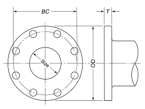
Waterworks valves, flanges and fittings historically were constructed of gray iron for operation up to about 250 psig. Because gray iron is brittle, waterworks flanges traditionally have been flat faced to reduce the bending loads on the flange. In other words, they mate to each other on the same plane radially from the inside diameter (ID) to the OD as shown in Figure 1. When bolting a cast iron flange to a raised face steel or ductile iron flange, low grade carbon steel bolts (ASTM A307 Grade B) should be used to avoid breaking the cast iron flange when tightening the bolts.
The performance of the gasket seal is related to the surface finish of the flanges. Surfaces can vary from rough cast to lapped glass-like surfaces. Historically, waterworks flange faces have been machined flat with shallow grooves to help the gasket seal and prevent gasket blowout. The AWWA C207 flange standard specifies a serrated finish―a surface finish with 250 to 500 micro-inch roughness. The micro-inch roughness is basically the vertical distance between the peaks and valleys of the machined surface. Five hundred micro-inches is about one fourth the thickness of paper so measurements are taken with an electronic quality instrument called a profilometer, which pulls a stylus or diamond needle across the surface to detect the peaks and valleys of the surface. Some inspectors also carry a metal inspection comparator plate, which they use to compare the flange face to the surface plate visually or by touch.
Customarily, flange faces are free of lining and coating materials except for rust preventive compound. On the other hand, AWWA C110 iron fittings can be serrated or smooth and may be coated. Many waterworks fittings and gate valves are coated with fusion bonded epoxy (FBE), which requires the flange faces to be coated because of the manufacturing process. The flanges are smooth, providing little friction for the gasket, thereby risking gasket blowout. Fabric reinforced gaskets, high tensile strength fiber gaskets, or special engineered gaskets may be needed for high pressure systems when flanges are coated.
FLANGE GASKETS
If all that was needed was to bolt two flanges together to obtain a tight seal, this action would be simple. Unfortunately, flanges are not flat so gaps, irregularities and waviness between mating surfaces can allow fluid leakage. The purpose of the gasket is to fill the voids and withstand the pressure forces of the internal fluid. To accomplish this, gaskets need to be compressible to conform to the surfaces of the flanges, yet have sufficient strength to prevent yielding from the bolt loads and pressure forces (ESA, 1998). Poor gaskets tend to relax or extrude, causing gasket compression to be lost over time resulting in a leaky joint. For a gasket to maintain a seal, the compression force on the gasket from the bolts must be maintained even after the bolts are stretched from hydrostatic end force, which tends to separate the mating flanges.
To meet these challenges, gaskets need to have certain properties to perform well in various applications. First, the material of the gasket must be compatible with the fluid media. As far as water systems, most gasket materials work well in cold water service though the gasket material still must resist over-compression and extrusion so its tensile strength is important. This strength is related to the hardness of the gasket expressed by a Shore A durometer. The durometer rubber hardness scale ranges from 0 and 100—a rubber band is about 20 durometers and a hockey puck is about 90. Rubber gaskets for flanges typically have a specified hardness of 70 or 80 durometers. The resilience of the gasket is measured by a compression set test for which a load is applied, and the recovery of the material is measured. Rubber is a unique material in that it does not compress―it displaces or cold flows. Because of this, if a rubber gasket is over-compressed, it will flow into the ID or OD of the flange connection. To avoid overflow, the compression of rubber gaskets should be limited to 25%. The rubber gasket will continue to bounce back and fill voids and gaps in the flanges over time.
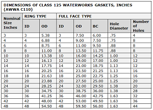
The AWWA C207 flange standard specifies the gasket be 1/16- or 1/8-inch thick, 80 durometers, red rubber for pressures up to 175 psig and fiber-type ring gaskets for 275 psig. Red rubber is typically a blend of styrene butadiene rubber (SBR). AWWA also specifies that fiber gaskets with rubber binder material is suitable for a seating stress of 3,000 psi to 15,000 psi. The dimensions of standard ring and full face gaskets for waterworks service are shown in Figure 2. The ID of these gaskets differs from those of steel pipeline gaskets (ASME B16.21) because steel fittings and pipe have different IDs than AWWA fittings. For example, an NPS 12 ASME gasket has an ID of 12.75 inches to match the OD of steel pipe (ASME B16.21). AWWA fittings have IDs that match the nominal size, 12 inches (AWWA C111).
In general, gaskets should be as thin as possible (Czernik, 1996). When a gasket is too thick, its diameter will change excessively when compressed. Also, a thicker gasket will deteriorate from the fluid media because of the greater exposed area. Finally, gaskets can blow out of the flange from internal pressure. The blowout forces are directly proportional to thickness, so when a thick gasket is used on flanges of low friction faces, blowout or outward extrusion may occur over time.
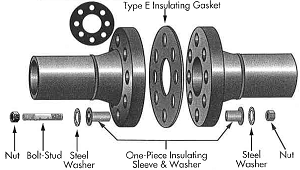
If the valve or fitting is to be used in a corrosive application such as desalinization, the valve or fitting may need to be protected from galvanic corrosion. Galvanic corrosion occurs between dissimilar metals such as iron and stainless steel in aggressive fluids such as when a battery-like electrical process occurs and the least corrosion-resistant material (e.g., an iron valve) is attacked. To prevent galvanic corrosion, special insulating gasket designs are used (Figure 3). Insulating gaskets are made up of full-face gaskets with insulating sleeves around the bolts and washers. The goal of an insulated joint is to break the metal-to-metal contact between two flanges. When insulating gasket assemblies are specified, the flange holes must sometimes be drilled oversize.
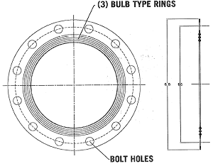
Finally, specially engineered gaskets have been designed for waterworks fittings that have the advantage of raised resilient beads or lips that seal with low gasket loads (Figure 4). The body of the gasket is constructed of a hard plastic such as phenolic. In these cases, the resilient portion is typically made of SBR rubber, which is common in the water industry. With this gasket, the bolt loads are low and the flange seal is forgiving and reliable.
FLANGE BOLT TORQUE
Bolts are an integral component of the flange assembly. These bolts must withstand the pressure load inside the pipe while maintaining a minimum load on the gasket. The pressure load is calculated by multiplying the area of the pipe and gasket times the maximum expected pressure. The calculated bolt load on an NPS 12 Class 125 flange at 250 psi can be as high as 50,000 pounds or 25 tons. This clearly shows why bolts have an important structural role.
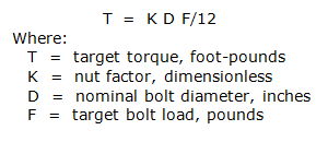
The load is divided by the number of bolts (for purposes of the example below, we’ve used 12 bolts). Each bolt must be tightened to share this load. For this example, a preload of at least 50,000/12 or 4,190 pounds is developed. The target bolt torque to produce a given load can be calculated using this formula:
For lubricated bolts, the nut factor is typically 0.20. Hence, for the subject example, the NPS 12 flange has 7/8 inch bolts whose torque can be calculated as follows:
This torque would be considered the minimum required to maintain a seal with a resilient gasket at 250 psig. A higher torque can be used, but at the risk of crushing the gasket. Most resilient gaskets are limited to a maximum load of 2,000 psi, unless fabric reinforced, in which case they can be 4,000 psi. Based on the area of the NPS 12 ring gasket, a 2,000 psi gasket load corresponds to an individual bolt load of 14,500 pounds and a resultant bolt torque of about 210 foot-pounds. Therefore, the NPS 12 flange bolts for a rubber gasket should be tightened in the range of 60 to 210 foot-pounds. As the bolts are tightened, the gasket compression should be monitored so that the gasket is not compressed to more than 25% of its original thickness. Rubber is incompressible, so when the gasket is loaded, the rubber flows to the ID and OD of the joint.
If a fiber-type gasket is used, the gasket compression can be much higher than the resilient gasket, typically 4,000 psi. Therefore, the bolt torques in the previous example could be double the resilient gasket torque or 420 foot-pounds.
There is an additional upper limit to the maximum bolt torque based on the strength of the bolt. Bolts for waterworks flanges are typically heavy hex carbon steel fasteners made in accordance with ASTM A307, Grade B, which specifies a tensile strength of 60,000 psi. A safe load for this bolt is 40,000 psi. Each bolt size has a specific tensile stress area; for example, the 7/8 inch bolt has a tensile stress area of 0.462 square inches. The corresponding maximum bolt torque based on the strength of the bolt can be found using this formula:
Hence, the ASTM A307, Grade B bolts are suitable for a resilient gasket target torque range of 60-210 foot-pounds. However, the bolts may not be sufficient for the load needed for a fiber gasket (420 foot-pounds). The next higher grade of bolt commonly used is ASTM A193 Grade B7, which is a chromium-molybdenum alloy steel with a tensile strength of 125,000 psi. The B7 grade is common for 275 psi applications and cases where high gasket loads are needed. ASME B16.1 recommends only B7 grade (low-strength) bolts for gray iron flanges to prevent damage to the flange. ASME B16.5 also discusses bolting to gray cast iron flanges and recommends control of the bolt torque and piping loads, using elastomeric or fiber gaskets, and using low-strength bolting.
Specially engineered gaskets often are used for waterworks fittings (Figure 4). Engineered gaskets seal under low gasket loads because of raised resilient beads or lips. The recommended bolt load for the NPS 12 engineered gasket is only 90 foot-pounds for 250 psi service and 110 foot-pounds for 350 psi service. With this gasket, the bolts really only need to support the pressure load and very little gasket load; which means lower bolt torques. Also, since these bolts have a hard shell, they cannot be over compressed.
The most common question valve and fitting manufacturers are asked is: what is the target bolt torque? Hopefully this article has showed that the target bolt torque is more a function of the gasket than the fitting or valve. Gasket manufacturers should provide a gasket load for the intended service. The gasket load can then be used to calculate the target bolt torque using the formulas above. Advice on how to install flanged fittings and valves follows:
INSTALLATION OF FLANGED FITTINGS AND VALVES
Care should be taken when installing flanged fittings and valves to prevent damage to equipment and to obtain a tight flanged connection. There are many obstacles to this endeavor including field conditions, misaligned pipe, valve weights, tolerances, and more. Unfortunately, few of the ASME or AWWA flange standards provide guidance on installation. The following guidelines are based on information provided in AWWA C110, ASME PCC-1, and general industry practices.
1. Bolting: Standards such as AWWA C110 provide information on the material, size, length and number of bolts. Certain valves have threaded holes that may require shorter bolts or studs in these holes. An engagement of at least one bolt diameter is typically used for the flange bolts in the tapped flange holes. When ring gaskets are used with gray iron flanges or when mating to raised face flanges, the bolt material should be low-strength steel such as ASTM A307 Grade B or SAE Grade 2 carbon steel. Higher strength bolts such as ASTM A193 Grade B7 would only be used with full-face gaskets or when high pressure service is needed.
2. Gaskets: Gaskets for waterworks service are typically ring or full-face synthetic SBR rubber and are 1/16 inch or 1/8 inch thick. Ring gaskets are recommended for NPS 14 and larger to improve sealing. Also available are special engineered gaskets with annular sealing rings, which greatly improve the gasket performance and reduce bolt torque needed.
3. Verify drilling: Inspect the mating flanges with a tape measure to verify that the bolt circle diameters of the two mating flanges match and the bolt set is appropriate for the through and tapped holes in the flanges (with consideration for washer thickness). Hard steel washers should be used to provide a solid surface for the nut to seat against. Flange outside diameters and thicknesses often vary but should not affect fit up.
4. Flange faces: Make sure flange faces are clean and not damaged. A scrape or mark across the flange face can cause a leaky joint. Do not use the flange to jack a fitting or pipe into place. Use large equipment anchored to the ground for positioning the pipe or fitting.
5. Lubricate: Lubricate the flange bolts or studs and insert them around the flange. Lubricate the internal nut threads and contact face. Lightly turn bolts until gaps are eliminated. Do not use the bolts to jack the flanges into alignment.
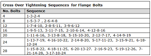
6. Torqueing: Starting with the bolt to the right of the vertical centerline. Number the bolts in sequential order in a clockwise direction (i.e., 1, 2, 3, 4, etc.). The torqueing of the bolts should then be done in three graduated steps (i.e., bouta 30%, 60%, and 100% of the target torque) using the cross-over tightening method. Cross-over tightening sequences for different number of bolts are shown in Figure 5.
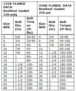
7. Check torque: When complete, check the torque on a rotational clockwise pattern until no further nut rotation occurs. If time permits, check the torque after 4-8 hours and repeat the clockwise pattern to restore the short-term relaxation of the gasket. Typical bolt torques for flanges with resilient gaskets are given in Figure 6. If leakage occurs, allow gaskets to absorb fluid and check torque and leakage after 24 hours. Do not exceed bolt rating or crush gasket more than 25 per cent of its thickness.
8. Records: Make a record of the flange connection for future reference including:
- Equipment identification
- Flange size and class
- Date of assembly
- Gasket material
- Bolt material
- Flange surface quality comments
- Target bolt torque and tools used
- Name of the pipe fitter
Recording the flange installation information facilitates future troubleshooting and repair of the joint.
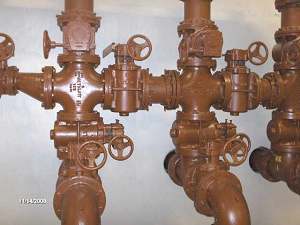
When all this is done, stand back and admire your work. You can see by the number of flanges shown in Figure 7, that flange design and installation plays an important role in piping systems.
CONCLUSION
Installing valves and flanges can make or break a piping system. To avoid serious construction problems and costs, follow published guidelines on the installation of bolts, gaskets for piping systems.
REFERENCES
1. American Society of Mechanical Engineers, ASME PCC-1-2013. Guidelines for Pressure Boundary Bolted Flange Joint Assembly.
2. American Water Works Association, ANSI/AWWA C110/A21.10-12 Ductile-Iron and Gray-Iron Fittings.
3. American Water Works Association, ANSI/AWWA C207-13 Steel Pipe Flanges for Waterworks Service – Sizes 4 In. Through 144 In.
4. ASTM International, ASTM A307 Standard Specification for Carbon Steel Bolts and Studs, 60 000 PSI Tensile Strength.
5. ASTM International, ASTM A193 Standard Specification for Alloy-Steel and Stainless Steel Bolting for High Temperature or High Pressure Service and Other Special Purpose Applications.
6. Czernik, Daniel E. Gaskets, Design, Selection, and Testing. McGraw-Hill, 1996.
7. European Sealing Association (ESA) and Fluid Sealing Association (FSA), Guidelines for safe seal usage – Flanges and Gaskets. 1998.
John V. Ballun, P.E. is the executive vice president and COO of Val-Matic Valve & Mfg. Corp. (www.valmatic.com). A mechanical engineer with over 40 years of valve design experience, Ballun has contributed to valve standards development work for American Society of Safety Engineers, AWWA, and Manufacturers Standardization Society (MSS). He is a past president of MSS and is a graduate of Illinois Institute of Technology with a BSE and Northern Illinois University with an MBA.
RELATED CONTENT
-
Proper Care of Knife Gate and Slurry Valves
How to resolve—and avoid—field failures of knife gate and slurry valves
-
The Misunderstood Check Valve
Too often this valve is unjustly blamed when problems occur, but the real culprit is its use in the wrong applications.
-
Hardfacing for Valves: Materials and Processes
Valve internals, such as seats and closures, are often at risk of erosion, abrasion, corrosion, galling and damage from cavitation.






 Unloading large gate valve.jpg;maxWidth=214)