Why Air Valves are Needed in Water Applications
Air valves are hydromechanical devices designed to automatically release air and wastewater gases or admit air during the filling, draining or operation of liquid piping systems for water and wastewater services.
#water-wastewater
OCCURRENCE AND EFFECT OF AIR AND WASTEWATER GASES
Water contains approximately 2% dissolved air or gas by volume at standard conditions (14.7 psia [101 kPa absolute] and 60°F [16°C])1 but can contain more, depending on the liquid pressure and temperature within the liquid piping system.
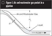
Wastewater systems can also contain more undissolved air and wastewater gases due to the decomposition of materials in the wastewater. Dissolved air and wastewater gases can come out of solution in pumps and in different locations along the liquid piping system where turbulence, hydraulic jumps and other pressure variation phenomena occur. Once out of solution, air and wastewater gases will not readily dissolve and will collect in pockets at high points along the liquid piping system.
Air and wastewater gases come out of solution in a liquid piping system due to low pressure zones created by partially open valves, cascading flow in a partially filled pipe, variations in flow velocity caused by changing pipe diameters or slopes, and changes in pipe elevation. Entrained air that reaches water service connections may be detrimental to the customer’s water systems.
An air and wastewater gas pocket may reduce the flow of liquid in a liquid piping system by reducing the cross-sectional flow area of the pipe, and if the volume of the air and wastewater gas pocket is sufficient, complete binding of the liquid piping system is possible, stopping the flow of liquid.2
SOURCES OF AIR AND WASTEWATER GASES
In addition to air and wastewater gases coming out of solution, air may enter liquid piping systems at leaky joints where the pressure within the liquid piping system falls below atmospheric pressure. These conditions exist in the vortex at the pump suction, at pump glands where negative pressure occurs and at all locations where the pipe elevation is above the hydraulic grade line.
Air may enter liquid piping systems through air/vacuum and combination air valves following complete pump shutdown, through the orifices of air-release valves installed in locations where the pressure is less than atmospheric and through pump suction pipes or inlet structures that are not properly designed to prevent vortexing. Finally, most vertical turbine and well pumps start with air and wastewater gases in the pump column as shown in Figure 2, which may pass by the check valve and flow into the liquid piping system with every pump start.
Air and wastewater gases entrainment is much greater in wastewater force main systems than in other pumped liquid transmission systems owing to their unique design and operational characteristics. Lift stations with wet wells or other sewage collection basins are a major source of entrained air and wastewater gases induced by plunging jets of sewage and by vortices of air and wastewater gases sucked into the pump. Because of the cyclic operation of force main systems, sections of the force mains empty out at the end of each pumping cycle, drawing air and wastewater gases into pipes. At the entrance to sewage lift stations, air and wastewater gases are entrained from plunging jets of sewage.
GAS POCKET BEHAVIOR
Four major factors influence entrained air and wastewater gas behavior in liquid piping systems: buoyancy, velocity, drag and equilibrium in surface tension between the liquid, air and wastewater gases, and the pipe wall. These factors, together with air and wastewater gas pocket size and concentration, influence the tendency of bubbles to aggregate and increase in size and determine the direction of their movement either with or opposite to the direction of liquid flow.
These factors also affect the entrained air and wastewater gases pockets’ influence on liquid flow capacity, head loss and energy consumption. In rising pipe sections and when there is no flow in the pipeline, buoyancy will force air and wastewater gas pockets of all sizes and shapes to travel to peaks or high points along the liquid pipeline. At down-sloping and level pipe sections, when buoyancy exceeds drag, the pockets will travel upward in the opposite direction to the flow. When drag exceeds buoyancy, the pockets will travel in the direction of liquid flow.
Large air and wastewater gas pockets traveling in opposite direction to the liquid flow often break up in flow due to buoyancy, resulting in smaller air and wastewater gas pockets, including bubbles, changing direction and being dragged in the direction of the liquid flow with the larger air and wastewater gas pockets or continuing to travel upstream against the flow. Pockets of air and wastewater gases traveling with the liquid stream also break up into smaller air and wastewater gas pockets and bubbles that disperse in the liquid stream, traveling in different velocities.
In all these cases, the air and wastewater gas pocket’s movement disturbs the flow where drag and turbulence increase head losses, resulting in decreased flow capacity and increased energy consumption.7
EDITOR’S NOTE: This article is Chapter 1 of the M51 Air Valves: Air Release, Air/Vacuum, and Combination, Second Edition by the American Water Works Association. The manual also covers specific types of air valves (see Chapter 2: Types of Air Valves), where they should be located, design of the valve orifice, the effects of water hammer and installation, operation, maintenance and safety of air valves. For information, go to www.awwa.org.
REFERENCES
- Dean, J.A. 1992. Lange’s Handbook of Chemistry, 14th ed. New York: McGraw-Hill.
- Karassik, I.J., J.P. Messina, P. Cooper, and C.C. Heald. 2008. Pump Handbook, 4th ed. New York: McGraw-Hill.
- Escarameia, M., C. Dabrowski, C. Gahan, and C. Lauchlan. 2005. Experimental and Numerical Studies on Movement of Air in Water Pipelines, Report SR 661, Release 3.0. Wallingford, Oxfordshire, UK: HR Wallingford Ltd.
- Jones, G.M., R.L. Sanks, G. Tchobanoglous, and B.E. Bosserman II, eds. 2008. Pumping Station Design, rev. 3rd ed. Boston: Butterworth-Heinemann.
- Edmunds, R.C. 1979. Air Binding in Pipes. Jour. AWWA, 71(5): 272–277.
- Pozos-Estrada, O. 2007. Investigation on the Effects of Entrained Air in Pipelines, Dissertation Volume 158. Stuttgart, Germany: Institute of Hydraulic Engineering Faculty of Civil and Environmental Engineering, Engineering and Allied Operations, Institut für Wasserbau der Universität Stuttgart.
- Lubbers, C.L., and F.H.L.R. Clemens. 2005. Capacity Reduction Caused by Air Intake at Wastewater Pumping Stations. In Proc. Water and Wastewater Pumping Stations Conference, April. Cranfield, UK: University of Cranfield.
RELATED CONTENT
-
CASE STUDY: Water Utilities Can Better Manage Flow Fluctuations with Single Rolling Diaphragm Valves
Without proper pressure management, high-pressure incidents can occur when pumps are turning on or off or when a valve suddenly closes, sending water hammer back through a piping system. Having the right valves to manage large fluctuations in water flow is one way that utilities can balance erratic flows and stay ahead of evolving community demands.
-
Ancient Roman Valves
The story of water supply in the ancient Roman Empire is grand.
-
The Basics of Eccentric Plug Valves
Wastewater systems present many challenges to pumps and valves because the flow can contain grit, solids and debris, depending where in the process the equipment is located.


 Unloading large gate valve.jpg;maxWidth=214)