Regardless of which drains, valves or piping assemblies are attached to the main valve, they must be designed and constructed in accordance with many of the same construction and design standards and codes as those of the base valve and piping system so they can safely handle the same conditions, including the same pressures and temperatures. The auxiliary piping is attached to the valve by either a mechanical (threaded) or welded connection.
WHAT THEY DO
Auxiliary connections may also sometimes improperly be used as steps for climbing on the piping system, so they must be built to be stout with the correct pipe thickness (schedule). This need for a very stout connection led to the creation of the extended body American Petroleum Institute (API) 602 (initially API 606) valve design standard in 1989. Such valves have extra thickness for strength as well as a much larger area for welding onto the base valve.
Many process applications introduce fluids that can become solids or semi-solids as they attach to the internal valve components. This situation occurs frequently for valves in coker service. If left alone, the coke becomes rock hard and will adhere to the internals of a valve. A common method to eliminate this coke buildup is to attach auxiliary connections that feed into the seating areas of the valve. These lines are then energized with pressurized steam that keeps the moving parts moving and the valve closure member (disc or ball) free to move. These steam injection lines are often used in other services where fluid solidification can seize the valve and prevent proper operation.
Steam injection lines are also used to “warm up” valves before high- temperature process fluid enters a cold, closed valve and a downstream pipeline, a situation that can cause thermal shock and potentially damaging stresses.
While drain lines are usually attached to the lowest point of the valve body, additional connections sometimes also are made to help the drain function. Many times, an additional connection is made near the top of the valve body or bonnet. This connection, combined with the lower drain connection, allows for a pressurized flushing action to occur in the valve body. The pressurized flushing can be used to remove traces of one fluid from the body before a different fluid is introduced in the piping system.
Double-block-and-bleed valves require a drain to accomplish the “bleed” function of that type of valve. These valves may have a single bottom drain or a secondary upper connection, depending on the application.
THE BYPASS
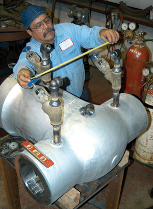
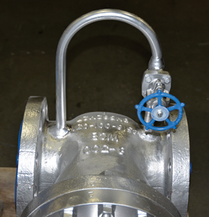
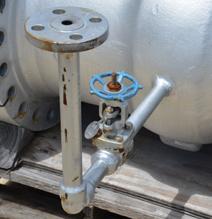
But just what is a bypass? A bypass is a small-diameter pipeline that runs from the upstream side of the valve closure element to the downstream side. Some bypass systems include connections to both sides of the closure element as well as to the valve body.
Valve manufacturers handled construction of bypasses in many cases by casting actual flanged bosses onto the valve body. Cast or bolted bypass valve assemblies were then used to connect the bypass to the valve body. One additional characteristic of these early-day bypasses is that they were usually much larger lines than are used today.
Probably the most popular use of a bypass is to warm up the downstream portion of a heated fluid or steam line. The slower flow of the small bypass line around the large main closure member allows the downstream portion of the line to warm up slowly, reducing the potential for temperature shock.
Bypass systems also can be used to roughly regulate the pressure in an upstream piping system. However, unless the bypass piping system is part of a control loop, accurate pressure regulation cannot be accomplished.
Another use for auxiliary connections is to attach gauges and other fluid-monitoring devices. Sometimes it’s much easier to add these connections to valves than to tap into the main piping system.
CONNECTING TO THE VALVE
To make a sound connection onto the valve, wall thickness has to be enough to allow for proper depth of the threaded or socket-welded connection. This means some smaller, thin-walled valves are not good candidates for auxiliary piping connections.
The American Society of Mechanical Engineers (ASME) B16.34, Valves- Flanged, Threaded, and Welding End, contains the rules by which many auxiliary connections are made. Here are some excerpts from that document pertaining to auxiliary piping connections:
6.3.1 General. Auxiliary connections, e.g., for bypass connections, shall be designed, fabricated, and examined so as to warrant at least the same pressure-temperature ratings of the valve.
6.3.2 Pipe Thread Tapping. Threads for threaded auxiliary connections may be tapped into the wall of a valve if the metal is thick enough to allow the effective thread length specified as shown in Figure 4 [of B16.34].
6.3.3 Socket Welding. Sockets for socket welding assembly of auxiliary connections may be provided in the wall of the valve if the metal is thick enough to accommodate the depth of the socket and the thickness of its shoulder as specified, as shown in Figure 5 [of B16.34]. Where the metal thickness is insufficient, or the socket opening requires reinforcement, a boss shall be added as shown in Figure 4 [of B16.34].
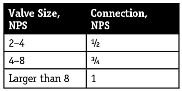
ASME B16.34 also contains this recommended table of minimum auxiliary connection sizes:
In the mid-20th century, the valve industry decided that some standardization in auxiliary piping locations was needed. The Manufacturers Standardization Society (MSS) responded in 1953 by creating SP-45, Bypass and Drain Connections. This document details the locations where auxiliary connections are preferred. In most cases, extra wall thickness (bosses) are provided at these points. The document has been updated over the years to include gate, globe, check, angle, plug and ball valves. MSS SP-45 also lists preferred locations for standard bypass installation if no specific location is specified in the purchase order.
END-USER REQUIREMENTS
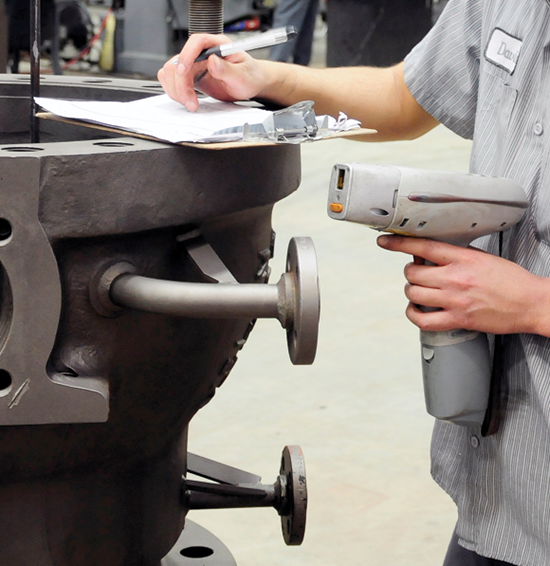
Some end-user/owner companies also have their own additional specifications for auxiliary valve connections. For example, some refiners require that auxiliary piping be reinforced with gussets. These gussets must be made of the same material as the valve and/or auxiliary piping.
Some additional end-user requirements include the seal-welding of certain threaded connections. One refiner requires that any threaded plugs or caps that are used only for hydrostatic testing that are in dangerous service be seal-welded. A minimum of two weld passes are required, and all threads must be covered.
One dimension that is still not standardized after all these years is the length that the loop of pipe sticks out from the main valve. Some end users specify this dimension, but many just leave it up to the OEM or the company installing the bypass.
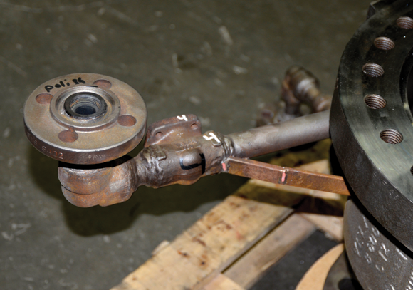
Large cast or ductile iron valves are still very popular for use in waterworks service. Many times, these valves require bypasses or other auxiliary connections as well. Since iron is not easily welded, threaded connections are used. This requires some old-school pipe-fitting to get all the pipe sections, fittings and bypass valves in proper alignment and leak-tight. These connections will usually also contain at least one union to assemble the piping assembly.
It is rare to see requirements for threaded bypasses on steel valves. The ease and efficacy of the welded connection is usually a much better choice.
WELDED CONNECTIONS
The typical procedure for socket welds requires that the connecting pipe be inserted into the socket (on the valve) and then backed slightly out before welding. This process ensures that thermal expansion will not cause cracks in the weldment.
Any required heat treatment per the applicable construction code must be performed as well. This can be tricky if the entire base valve and piping containing a valve is furnace heat treated. The furnace heat treatment can sometimes cause an auxiliary valve’s seats to become loose, requiring replacement of the valve and reinstallation of the piping assembly. Localized heat treatment using blanket or band-type heaters can lower the risk of possible valve damage, but the process is more cumbersome.
Another welding process sometimes required in auxiliary piping attachments to valves is the creation of bosses where none exist. This process requires buildup of a pad of the appropriate weld metal to the required thickness, followed by cosmetic grinding of the weldment.
Sometimes an end user will require that a special outlet fitting such as a socket-weld or threaded outlet be welded to the valve and then the auxiliary piping attached to the fitting. These fittings can help if the wall thickness of the base valve is minimal and added strength is desired in the weldment.
Pipeline valves almost always have some form of auxiliary connection. These can be emergency seat lubrication ports or drain lines. For valves installed above ground, simple check valves or injection-type fittings are threaded directly into the valve body. For buried valves, welded pipe connections are usually employed. Such pipelines are required to elevate the seat injection and drain lines up to the surface.
When permitted by the owner, auxiliary connections are also sometimes made for emergencies, particularly to inject compounds into leaking valves to stop gasket leaks. These connections are drilled and tapped, and button-head-type check valve fittings are installed to allow sealant to be injected into the leak area. An additional emergency connection is also sometimes made in the packing gland of the valve. This connection is used to inject packing sealant into a leaking valve that is causing excessive fugitive emissions leakage. As in all industrial practices, strict adherence to safety standards and procedures is required.
GREG JOHNSON is president of United Valve (www.unitedvalve.com) in Houston. He is a contributing editor to VALVE Magazine, a past chairman of the Valve Repair Council and a current VRC board member. He also serves as chairman of the VMA Communications Committee, is a founding member of the VMA Education & Training Committee and is past president of the Manufacturers Standardization Society. Reach him at greg1950@unitedvalve.com.
RELATED CONTENT
-
Ancient Roman Valves
The story of water supply in the ancient Roman Empire is grand.
-
The Misunderstood Check Valve
Too often this valve is unjustly blamed when problems occur, but the real culprit is its use in the wrong applications.
-
Air Valves in Piping Systems
Liquid piping systems are prone to collecting air from incoming fluids, pumps and connections.




 Unloading large gate valve.jpg;maxWidth=214)