


Published December 15, 2025
Discover how single-piston effect (SPE) and dual-piston effect (DPE) seat designs are engineered to meet the demanding pressures and temperatures of subsea applications.
By Mike Hedger, Director of Engineering, CDI Products
Subsea oil and gas production environments impose extreme demands on valve performance requiring robust sealing systems to ensure operational reliability, safety and environmental compliance. Valves in these applications must meet qualification testing with pressures up to 10,000 psi, temperatures from -40°F to over 400°F, in order to ensure leak-tight isolation in application for decades without maintenance. Ball and gate valves, critical for flow control and emergency shutdowns, rely on advanced seat designs, particularly Single Piston Effect (SPE) and Dual Piston Effect (DPE) configurations, to meet these challenges.
The American Petroleum Institute (API) standards, specifically API 6D and API 6DSS, govern the design, testing, and performance of Double Block and Bleed (DBB) and Double Isolation and Bleed (DIB) valves for surface and subsea pipeline applications. These standards help to ensure valve isolation integrity under extreme temperature and pressure conditions.
Compliance with these standards ensures subsea valves can withstand pressures up to 10,000 psi and operate reliably at depths exceeding 9,000 feet, minimizing risks of leaks or failures, and preventing costly interventions.
API 6D and 6DSS specify configurations for DBB and DIB valves based on SPE and DPE seat combinations, tailored for subsea performance. The table below outlines these configurations:
|
Configuration |
Seal Combination |
Key Characteristics |
Subsea Applications and Relief Requirements |
|
DBB |
Both seats SPE |
Seals against pressure from either direction; automatically relieves cavity pressure to the lower pressure side. Does not provide double isolation if one seat fails. |
Used in subsea pipelines for maintenance or non-critical isolation; self-relieving design eliminates need for external relief, simplifying system design. |
|
DIB-1 |
Both seats DPE |
Provides true double isolation with bidirectional sealing on both seats. Traps cavity pressure, requiring external relief. |
Critical for subsea applications requiring maximum isolation (e.g., high-pressure gas lines); requires external relief systems (e.g., relief valves or vent piping) to manage cavity pressure. |
|
DIB-2 |
One seat SPE, one seat DPE |
DPE seat provides bidirectional isolation; SPE seat allows self-relief on one side, reducing cavity pressure issues. |
Suitable for subsea systems needing strong isolation with partial self-relief; external relief may be needed depending on valve orientation and pressure conditions. |
These configurations undergo rigorous testing, including hyperbaric and high-pressure seat tests, to ensure sealing integrity. Valves are marked (e.g., DBB, DIB-1, DIB-2) to indicate compliance and guide installation in subsea manifolds or flowlines.
The selection of double block and bleed (DBB), double isolation and bleed-1 (DIB-1), or double isolation and bleed-2 (DIB-2) valve configurations depends on the valve’s operational role, environmental conditions and system redundancy requirements.
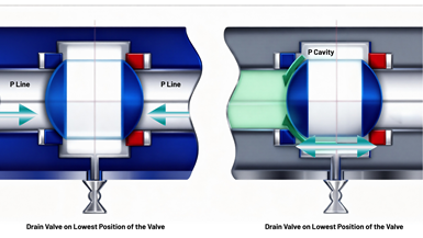
Flow direction for ball valves for SPE and DPE seat seals. Source: CDI
DBB valves, designed to provide two sealing barriers and a bleed point, are often used in flowline applications where cost and simplicity are prioritized, ensuring effective isolation with a single valve body.
DIB-1 valves, which offer bidirectional sealing on one seat and unidirectional sealing on the other, are suited for subsea trees where enhanced isolation is needed under specific flow conditions.
DIB-2 valves, with both seats providing bidirectional sealing, are typically specified for critical emergency shutdown valves (ESDVs) to ensure fail-safe isolation regardless of pressure direction, minimizing the risk of fluid loss or environmental damage.

An engineer reviews unidirectional seat seal design. Source: CDI
To withstand subsea extremes—pressures depths up to 9,500 ft and internal pressures up to 10,000 psi, temperatures up to 400°F, and aggressive media like sour gas—SPE and DPE seats incorporate advanced sealing technologies such as spring-energized seals and V-ring live loaded seals.
Seal failures in subsea valves can lead to significant operational, safety, and environmental consequences, with distinct impacts based on seat type and location.
|
Configuration |
Position |
Failed Seat Type |
Main Effects |
Key Concerns Beyond Leakage |
|
DBB |
Upstream |
SPE |
Cavity leakage, external vent relieves; no downstream leak if downstream holds. |
Loss of redundancy; environmental vent risks; operational disruption. |
|
DBB |
Downstream |
SPE |
Downstream leakage, external vent partially relieves. |
Isolation failure; safety/environmental hazards. |
|
DIB-1 |
Upstream |
DPE |
Cavity buildup vented externally; downstream DPE seals (no downstream leak). |
Redundancy loss; fluid trapping. |
|
DIB-1 |
Downstream |
DPE |
Downstream leakage possible; external vent relieves. |
Isolation compromise; maintenance risks. |
|
DIB-2 |
Upstream |
SPE |
Cavity leakage, self-relieves upstream; downstream DPE seals (no downstream leak). |
Redundancy loss; fluid cycling/wear. |
|
DIB-2 |
Downstream |
DPE |
Downstream leakage; internal relief to upstream. |
Isolation failure; environmental release. |
Choosing the correct seal types and configurations is paramount to ensuring performance as well as compliance with API standards. Users should work with their valve OEM or sales partner to ensure that the valves selected meet the requirements for their applications, including materials for the specific media that will be flowing through the valves and the applications where the valves will be used. Suppliers should make testing reports available upon request to ensure that all products meet the end-user’s specifications for the application. Using the correct products is the best way to ensure the integrity of the valve and protect the system, employees and the environment from product failures or malfunction due to incorrect specifications.
Mike Hedger is director of product management at CDI Products. He previously was director of engineering, and has nearly two decades of experience with high-tech polymer materials and specialized product design for sealing and bearing systems in various industries.


June 5, 2026
Why engineered mounting kits are critical to valve automation integrity.
April 7, 2026
Simple automations can create big gains on the shop floor.
April 3, 2026
