Controlling Our Water Systems, Part II
To better understand the actuators and controls in our water systems, we discussed the types and some of the considerations for sizing in the first part of this article, which appeared in the print version of VALVEMagazine and is posted here.
#actuators #controls #water-wastewater
POSITION CHARACTERISTICS
It is important to understand the seating characteristics of a valve requiring power actuation. Some types of valves, such as gate valves, are commonly referred to as torque-seated because they are seated by applying a specified torque to the stem. Other valves, such as resilient-seated butterfly valves, are commonly referred to as position-seated because they are seated by accurately positioning the closure member.
Slide gates are driven into the seat and closed by the actuator. The stroke of the actuator can be adjusted to provide the best seated position to minimize leakage. Butterfly and ball valves require precise rotational positioning to affect a tight seal, typically within plus or minus one-half of a degree. Certain types of double and triple offset butterfly valves seal tighter as they are closed further into the seat, so the manufacturer will need to specify whether these types of valves should be position seated or torque seated. Similarly, eccentric plug valves seal tighter as they are closed further. They are sometimes rotated up to 5 degrees past closed to create a seal under high reverse pressures or after plug wear has occurred. The manufacturer’s instruction manual should be consulted for the proper method to adjust the closed setting for these valves.
SIZING CONSIDERATIONS
AWWA valve standards require the valve manufacturer to provide the minimum required shaft torque (MRST) values to operate a valve through the entire opening and closing strokes. The MRST values are calculated using the methods described in AWWA Manual M49.
The torque at both the seated position (seating and unseating) and the mid-stroke maximum total dynamic run (opening or closing) are evaluated. The actuator manufacturer calculates the actuator sizing torque (AST) based on the MRST times the application factors (AF) given in Table 1. The use of the application factors ensures actuator operation over the life of the valve as controls are added, operating conditions change or friction in the valve or actuator increases over time. Valves in the waterworks industry have a typical operating range of 33°F‒125°F (0.6°C‒51.7°C). Temperature can affect valve-seating torques and friction factors for bearings in the valve and actuator.
Similarly, if the valve and actuator assembly was designed for clean water service but is being used in wastewater service with some solids, then the valve torques may increase. The valve manufacturer should be advised when the valve medium is different than standard or when operating temperatures are near the extremes or exceed the extremes of this range.
ACTUATOR TORQUE CHARACTERISTICS
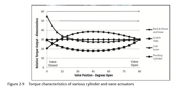
Depending on the type of quarter-turn actuator mechanism employed, the torque output versus angle of the actuator position may vary with stroke, as illustrated in Figure 2-9. For purposes of comparison, all of the torque curves were adjusted to provide the same torque at the 90-degree position. The change in torque output as the actuator is closed can then be comparatively illustrated. The rack-and-pinion and vane-type mechanisms produce constant torque throughout their travel. Their characteristic curve is shown as a straight horizontal line in the figure. The scotch-yoke mechanism will typically produce higher torques at both ends of travel. The scotch-yoke curve typically is curved downward in the middle of the stroke, as shown in the figure.
Some models may have a canted or slanted slot in the lever, which may provide a greater torque multiplier on one end than the other. If the valve has a higher actuator sizing torque in mid-travel versus at the seat end, then a larger than expected scotch-yoke actuator may be needed. The link lever will produce higher torques at one end with the higher torque typically used to seat and unseat the valve. Because of higher torque capability on one end than the other, it is important to match the closed position of the actuator with the closed position of the valve, if the increased torque is needed to seat the valve.
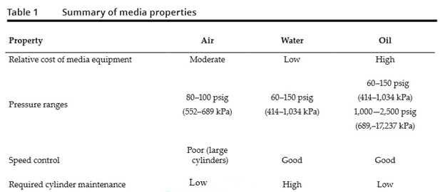
Link-lever actuators are often economical for valves with high seating torque in the closed position, such as butterfly and ball valves. The pivoting cylinder actuator will produce higher torques near mid-travel. Pivoting cylinder actuators are used on large valves where the mid-travel torque is often high because of torques related to flow through the valve. The actual torque rating of the actuator will depend on its size and supply pressure. The supply pressure varies depending on the supply media system employed. Many applications specify a minimum or range of supply pressures, such as 40‒80 psig (276‒552 kPa). In these cases, the actuator sizing should be based on the minimum pressure.
Actuator manufacturers publish tables of actuator torque versus supply pressure, as shown in Table 2, which are compared to the valve actuator sizing torque.
Pneumatic and hydraulic actuators with springs referred to as single-acting require special sizing considerations. The cylinder must create enough thrust to operate the valve while simultaneously compressing the spring. When the spring is needed to operate the valve, the spring force diminishes as the actuator strokes. Actuator suppliers publish torque capabilities of their actuators with and without the spring forces (Table 2).
The torque output is shown for the Start, Mid and End positions. Start equates to the travel position where the spring is compressed. Mid shows the minimum torque in the center of travel, and End represents the torque at the far end of travel with the spring fully extended. The values shown in Table 2 are typical for a scotch yoke-type actuator where the torque output is less in the Mid positions. Also, the torque is reduced from start to end because as the spring extends and relaxes, its force lessens.
Note that as the air supply pressure increases, so does the output torque proportionally. The air supply pressure is limited because using pressures higher than 80 psi (552 kPa) generates torques that exceed the capability of the lever mechanism. This is common for many actuators.
EXAMPLE: Select the single-acting fail-closed actuator model that will operate a butterfly valve with a running torque of 708 ft-lb (960 N-m), a break torque of 1,079 ft-lb (1,463 N-m), and an 80-psig (552 kPa) minimum cylinder supply pressure.
First, a 1.25 safety factor is applied to the torques, yielding a break sizing torque of 1,349 ft-lb (1,829 N-m) and a run sizing torque of 885 ft-lb (1,200 N-m). Second, the run sizing torque 885 ft-lb (1,200 N-m) is compared to the Mid torques listed in the 80-psig (552 kPa) column, and the Model B is shown to generate 1,117 ft-lb (1,514 N-m) at 80 psig (552 kPa) in the Mid positions. Third, the break sizing torque (1,349 ft-lb [1,829 N-m]) is compared to the End torques listed in the 80-psig (552 kPa) column and the Model B is shown to generate 1,241 ft-lb (1,683 N-m) for the end position. The Model B would be selected for this example.
Because spring-return cylinders must be sized to overcome the spring force and the valve torque at the minimum supply pressure, the units may become dimensionally large and powerful. There may be a risk to the valve with such a powerful actuator, especially when it is sized at the minimum supply pressure but powered with the maximum supply pressure in the field.
Finally, because spring-return actuators can be physically large and heavy, users should verify that there is sufficient space around the final installation to accommodate the actuator and its operation and maintenance. If the valve stem is horizontal, it may be necessary to provide secondary actuator support. If the valve is obstructed from closing, the actuator may have sufficient torque to exceed the maximum acceptable stem torque (MAST) specified by the valve manufacturer. When critical shutoff valves are specified, the actuator sizing may also need to consider the MAST of the valve.
For information on this report, go to www.awwa.org.
RELATED CONTENT
-
Check Valve Installation Considerations to Maximize Process Performance
Key considerations in successful check valve performance.
-
Water Hammer
Water hammer is a shock wave transmitted through fluid contained in a piping system.
-
New Requirements for Actuator Sizing
After decades of confusion, the American Water Works Association has created new standards for actuator sizing that clear up some of the confusion and also provide guidance on where safety factors need to be applied.


 Unloading large gate valve.jpg;maxWidth=214)