Evolution of Butterfly Valves on Aircraft Carriers
Butterfly valves are an integral part of keeping an aircraft carrier’s firemain system operating smoothly.
#ball-butterfly-plug #automation #knowyourvalves
THE FIREMAIN SYSTEM
The firemain systems aboard carriers distribute pressurized seawater for firefighting, cooling and washdown services. The firefighting services aboard these ships include fire hose stations, foam stations and fire protection service for compartments that store flammable material. Foam stations inject a mixture of foam and seawater, which is distributed to areas where risk of flammable liquid spills or fire exists such as the hangar bay, flight deck, machinery room and aviation fuel pump room bilges.
The firemain is one of the most mission-critical fluid distribution systems aboard any naval combatant. It provides a cooling medium for key equipment including jet blast deflectors—the safety devices on jet planes that redirect the high energy exhaust. The main also provides chemical, biological and radiological washdown countermeasures as well as water for cooling down auxiliary machinery, eductors (pumps), ship stabilization equipment and flushing for urinals and commodes.
Because it is so critical to the entire ship’s water flow, the isolation valves in firemains are designed not only to enable routine maintenance, but more importantly, to continue support for the ship and its crew after a system incurs battle damage.
I remember in the early 1990s when I was serving as the chief engineer of the USS Nimitz (CVN-68), my team pointed out an old-style butterfly valve that would not cycle. After many attempts, it was leaking saltwater in one of the main passageways on the carrier. When I visited the location of the valve, I saw the handle broken off completely. My guess is that my team had used a “cheater bar” to maximize torque on the valve in a vain attempt to cycle it. Because of the potential impact to operations from this one, non-functioning valve, we had to attempt maintenance action only while the ship was berthed in port. Our team made plans to tag out additional butterfly valves up- and downstream to isolate, then remove and replace the bad valve.
The ship eventually moored in Bremerton, WA, where the team attempted the repair. Hours passed, and the supervisor of the repair effort reported they had already closed and tagged out three or four valves up- and downstream of the broken valve without a decrease in pressure. I received the ship captain’s permission to shut down shore-supplied firemain water. Once the system was drained (several hours later), the repair could be completed. We found out the valve would not cycle because it was packed with mussels, barnacles and other debris as well as pieces of seat material from other butterfly valves.
At the time I wondered why we had such ineffective valves on such a critical system. The firemain is vital to the ship’s mission, which is to launch aircraft to achieve the objectives of the National Command Authority.
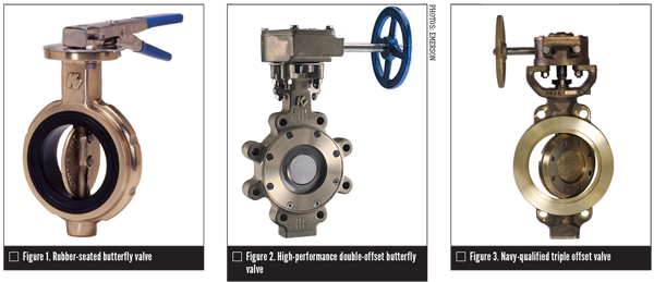
The type of butterfly valve aboard the Nimitz at the time was a rubber-seated butterfly valve (Figure 1). As the valve was cycled, the valve disc was always in contact with the seating surface, an action described as a “zero offset butterfly valve.” Since the seating material was always rubbing against the disc with each cycle, erosion of the seating surface was common. Combine that with the high density of calcareous sea life resisting the valve’s movement and damaging the seat and it’s easy to see why these valves failed often. Considering the fact the double offset valve military specification for shipboard butterfly valves was issued in 1983, it’s surprising the Nimitz still had these older valves aboard. New construction carriers most probably were already being outfitted with improved butterfly valves and in-service carriers were scheduled to be upgraded going forward.
The Navy’s 1983 defined military specification (MIL-V-24624) for shipboard butterfly valves represented a major improvement over the zero offset butterfly valve. The specification required the double offset feature (Figure 2). Generally, the first offset is achieved by locating the shafts downstream of the centerline of the seat. This allows a totally unobstructed 360-degree sealing surface. The second offset locates the shafts off-center of the vertical axis of the seat. The combination of these two offsets creates a camming effect as the disc swings into and out of the seat.
The disc lifts quickly out of the seat in the first few degrees of travel and does not contact the seat again until it is nearly closed. No wear points exist between the seat and disc.
The double offset valve enjoys reduced operating torques and a substantially extended seat life. This valve has become widely known as a high-performance butterfly valve and is in great demand even today on almost all surface combatants, including aircraft carriers. However, despite its benefits, this valve often requires piping modifications because it uses gasket material on both sides, and it sometimes does not fit into the space remaining when a resilient or rubber-seated butterfly valve is being replaced. Industry stepped up to address that issue with the next upgrade of this valve.
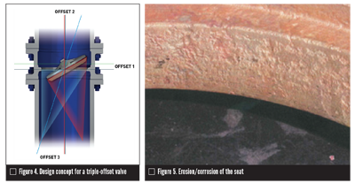
This next improvement was the triple offset torque-seated valve (TOTS), which has a metal-to-metal seat and a quarter-turn, non-rubbing rotation (Figures 3 and 4).
Torque seating means that the seating force is generated by externally applied torque rather than by mechanical interference. Cone-to-cone sealing occurs by contact pressure and not by friction generated by the rubbing between the valve disc and seat.
The TOTS valve also has the double offset features of the MIL-V-24624 valve, but a third offset was created. This third offset is where the seat and seal cone centerlines are inclined with respect to the pipe/valve centerline. This offset eliminates rubbing completely, yet still results in zero leakage. These features result in longer life expectancy, minimum maintenance requirements, and a lower cost of ownership compared to traditional gate, butterfly and other valve designs. In addition, because there is no requirement for gaskets, the TOTS will usually fit perfectly into the space vacated by an older-style butterfly valve.
In 2003, the aircraft carrier program manager approved a ship alteration and specifically declared that the purpose of that alteration was to replace 20 existing butterfly valves with TOTS butterfly valves in key locations throughout the firemain system. These valves were intended to replace major isolation branches only (not this author’s emphasis). TOTS valves are generally more expensive to manufacture so it made sense to ensure the most important points of isolation for a firemain system, which has miles of piping across the ship, should have the most efficient and functional isolation valves. TOTS valves are the “Cadillac” of butterfly valves, and they function extremely well in the harshest of environments. Still, industry continued to improve on this Cadillac.
The most modern and even-more resilient butterfly valve is an interesting and unique version that addresses one of the slight weaknesses in -nickel-aluminum-bronze valves—the erosion/corrosion of the seat. (Figure 5 shows evidence of this on a TOTS seat).
The next generation of TOTS has a reinforced or hardened seat. This is accomplished by using cold spray technology, which takes small particles in the solid state of Inconel 624 and accelerates them to over 3,000 feet per second. The result is a coating on the base material. This generation of TOTS has a half-millimeter thickness of material that provides a substantial increase in hardness and is more than a 2000% improvement in resistance to erosion/corrosion. At this rate, it would take hundreds of years to wear away the cold spray covering (excluding foreign object seat damage).
CONCLUSION
Every U.S. Navy combatant ship depends on a good system of isolation for both maintenance and casualty control. Imagine if that bad valve on the Nimitz had failed catastrophically. With an inability to isolate that system (since several valves both upstream and downstream were not holding), it would have been challenging to stop the flooding. The only way may have been to eliminate firemain pressure almost completely for most, if not all the ship. If that had happened while our ship was deployed, the impact would have been extensive: flooded spaces, loss of use of a few catapults, loss of cooling for nearly all auxiliary systems. The list could go on and on. It probably would not have been a mission kill because the depth of talent and training of the crew in casualty control would have enabled them to correct the problem and restore the firemain. However, for a brief time, it would have degraded the readiness of one of the nation’s most important assets.
Because of how critical butterfly valve performance is to the fleet, the U.S. Navy has pushed industry to continue to improve on these valves. Thankfully, industry has responded, with today’s top performer the triple offset torque-seated (hardened seat) variant—the finest high-performance butterfly valve in the world.
MARK PETERSEN-OVERTON is a retired captain from the U.S. Navy, who is currently vice president of operations for ESI Acquisition Corp. doing business as JA Moody. Reach him at MPetersen-Overton@jamoody.com.
RELATED CONTENT
-
Operational Basics of Safety Valves
These spring-loaded valves provide overpressure protection for downstream equipment.
-
An Introduction to Axial Flow Check Valves
Check valves are self-actualizing devices that respond to both pressure and flow changes in a piping system.
-
Pinch Valves: An Uncomplicated Valve With an Important Purpose
Used in on/off or throttling applications, choosing the right style pinch valve depends on the application.


 Unloading large gate valve.jpg;maxWidth=214)