


The Final Control Element: Controlling Energy Transformation
When selecting control valves, be sure to properly evaluate the process conditions to identify potential issues and select the proper management techniques.
#controls #knowyourvalves
Share
Though digital instrumentation and process control systems have greatly improved over the years, process fluids are ultimately controlled by mechanical components. The control valve acts as the final element in a process control loop that influences process variables like pressure, temperature and flowrate. These are designed to modulate on a continuous basis in response to a variable command signal from the control system. This continuous control subjects them to more rigorous wear than on/off valves or isolation valves, which have different design details. Theoretically, any valve, actuator and positioner combination can adjust its position in response to a control signal that will affect the fluid stream. Depending on the process control loop, consider duty cycle, stroke speed, sensitivity, resolution, installed gain and the conservation of energy. Choosing the wrong control valve can lead to an unstable process control loop, process variability, excessive wear and catastrophic failure.

Figure 1. Single-stage compressible fluid. Figure 2. Stage compressible fluid.
CONTROL VALVE ACTUATION
Actuation is generally selected according to the valve type and is sized by the vendor. A pneumatic calculation is used based on valve requirements and minimum available air pressure. A safety factor of up to 50% is usually included based on characteristics of the service and the likelihood of restricted movement. The valve positioner is the device that modulates (strokes) the valve, moving it to the desired point of travel based on the command/input signal. The positioner is chosen by input type and desired diagnostics. High performance is often available for applications when position accuracy and response time are critical. Additional instruments such as limit switches, switching valves and solenoids may be included for feedback or failure mode.
MANAGING ENERGY TRANSFORMATION
The law of conversation of energy means that energy can neither be created nor destroyed; rather, it can only be transformed or transferred from one form to another. A fluid stream contains both potential energy in the form of pressure and temperature as well as kinetic energy in the form of motion. When the fluid stream goes through a restriction in the flow path—the control valve—potential energy is converted to kinetic energy. Potential energy is decreased by a reduction in pressure, and possibly temperature. Kinetic energy is increased through an increase in average velocity. Additional potential energy is expended on the production of vibration and possibly a phase change in the fluid. The internal trim components of the control valve must have the appropriate geometry and materials to manage the energy transformation. A properly selected control valve will manage the energy transformation, preventing excessive noise and vibration, and managing or eliminating a fluid phase change.
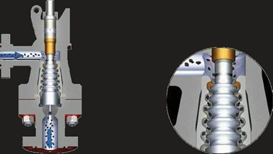
Figure 3. Multistage dirty service compressible fluid. Figure 4. Expanding area axial flow.
MANAGING CLEAN AND DIRTY COMPRESSIBLE FLUIDS
In the case of high-pressure drop with compressible fluids aerodynamic, noise can be generated across the control valve causing vibration, which leads to metal fatigue. Broken valve stems, actuator yokes, and accessory mounting hardware failures can result from damaging vibration generated by aerodynamic noise. Also, Occupational Safety and Health Administration (OSHA) regulations may require the use of additional PPE (personal protection equipment)—hearing protection—if sound levels are excessive.
Source control of aerodynamic noise can be accomplished through flow division. One example of this is “drilled hole technology,” which is a design that many control valve manufacturers use to control or eliminate the generation of aerodynamic noise when the fluid moves through the valve trim (Figure 1). Flow division means that instead of having the flow pass through a single opening, the flow is divided into multiple smaller flow streams by passing through several openings in parallel. Every time you double the number of openings, you reduce the noise by approximately 3 dBA. The noise reduction occurs primarily because the smaller openings shift the noise to a higher frequency. Higher frequencies are attenuated more than lower frequencies as the sound passes through the pipe wall. The smaller the diameter of the holes the higher the frequency shift. Also, because the human ear (and the “A” weighting curve on noise meters) attenuate higher frequencies, both the measured and perceived noise is decreased. Additional sound reduction can be obtained by staging the pressure drop (Figure 2). Since each stage will take only a portion of the total pressure drop, each will produce less vibration. The sum of the vibration from the total stages will be less than the vibration from a single stage.
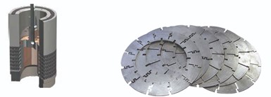
Figure 5. Multi-stack plate clean compressible fluid. Figure 6. Laser-cut stack disks.
In the case of high-pressure drop with a dirty compressible fluid, the typical drilled hole method would potentially clog, so pressure drop staging is the only method of source control of aerodynamic noise. As noted above, in pressure drop staging instead of taking the entire pressure drop in one step, the pressure drop is divided up into multiple steps (Figure 3). When the pressure drop is taken in more than one step, the individual velocity peaks are smaller than the velocity peak that would result from a single stage pressure drop. Because of the strong relationship between noise and velocity, small reductions in velocity can have a large effect on reducing the noise. For dirty fluids, an axial flow design is more typical. The flow passes down the valve taking numerous turns around the multiple stages on the plug. Since the design does not incorporate any small holes, particulate can pass unimpeded. Generally, it is necessary for the stages to increase in a cross-sectional area as the volume of the flow increases with each pressure drop (Figure 4).
Pressure drop staging can be obtained through multiple methods. For clean fluids, the typical radial flow pattern can be maintained with multiple concentric drilled hole cages. For applications with large mass flow rates and high differential pressures drilled hole trim designs no longer provides an adequate solution. Higher numbers of stages, and thus higher levels of noise reduction, can be obtained through stacked plate designs that incorporate a combination of fluid turning losses and contracting/expanding areas in the stack. Fluid paths can be a single plane or multiplanar and use as many as 36 stages depending on the manufacturer (Figure 5). Laser cutting of plates provides a large degree of design flexibility for staging and Cv requirements as well as a cost-effective means of machining the cutouts and notches that form the flow passages required (Figure 6).
MANAGING CLEAN AND DIRTY NON-COMPRESSIBLE FLUIDS
For non-compressible fluids, if the pressure drop is a high percentage of the inlet pressure, or the outlet pressure is close to or below the vapor pressure, there is potential for the fluid to change phase. Phase changes include cavitation and flashing. Fluid phase changes can cause significant damage to the control valve internals and downstream piping leading to reduced time between maintenance intervals and catastrophic failure.
In cavitation, the pressure drops below the fluid vapor pressure as it exits the port and changes from a liquid to a gas. On subsequent pressure recovery, as the fluid velocity decreases in the body gallery or downstream pipe, the fluid changes back into a liquid. The collapse of the bubbles releases a significant amount of energy that can be extremely damaging if it occurs in contact with the valve or pipe surfaces.
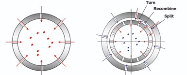
Figure 7. Single-stage cavitation containment. Figure 8. Double-stage cavitation containment.
As with aerodynamic noise reduction, the most common method for cavitation control with a clean fluid is “drilled hole” technology. The fluid is divided into multiple discrete flow paths, constricted, expanded and collided into diametrically opposed flow paths that prevent the damaging effects of cavitation (Figure 7). Dividing the flow through multiple holes with a small diameter limits the size of the cavitation bubbles. The smaller bubbles individually contain significantly less energy and collapse sooner than larger bubbles. By managing the trim velocity and directing the bubbles into the center of the flow stream they will collapse before they can impinge on any surfaces. By collapsing in the middle of the flow stream they will not damage any components and the generated noise will be muffled. Multiple concentric cages can be used to reduce the energy drop across the last stage, also reducing the energy level of any potential cavitation (Figure 8).
In dirty service non-compressible fluids, a source treatment is needed to eliminate cavitation while allowing particulate to pass unimpeded (Figure 9). In these cases, small holes cannot be used to minimize the energy of the bubbles. A multi-stage axial flow technology is designed to stage the pressure drop so the line pressure on the final stage stays above the fluid vapor pressure, thus eliminating cavitation entirely. Flow is divided, recombined, turned, constricted and expanded, thereby reducing fluid velocity, reducing static pressure loss and energy conversion on each stage (Figure 10).
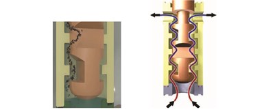
Figure 9. Non-compressible dirty service cavitation elimination. Figure 10. Non-compressible cavitation elimination.
MANAGING FLUID PHASE CHANGE
In non-compressible fluid applications where the outlet pressure is below the vapor pressure, a phase change cannot be avoided. As the fluid passes the restriction it will convert from a liquid to a gas. The energy required for the phase change will reduce the temperature of the fluid, thus reducing the vapor pressure, and a balance will be achieved where only a percentage of the fluid will change phase. If the outlet pressure is close to the vapor pressure only a small percentage will convert to gas. In these instances, damage can generally be minimized simply by using hardened materials.
In applications where the outlet pressure is considerably lower than the vapor pressure, such as boiler blowdown, the percentage of flashing will be significant. In these instances, hardened materials will be insufficient to provide proper protection but a different valve geometry can be applied to reduce or eliminate damage due to the flashing in the fluid stream. With a standard globe valve the fluid will change phase as it passes through the port and generate a high-velocity stream directed into the wall of the valve body. The geometry of angle valves and eccentric plug valves allows the fluid to exit directly from the valve without any turns (Figures 11 and 12). These eliminate the potential for valve body damage by allowing the fluid to flash directly into the downstream piping.
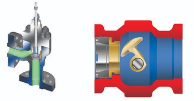
Figure 11. Angle pattern flow geometry flashing service. Figure 12. Eccentric rotary control valve flashing service.
For more severe applications, using a Venturi outlet will reduce turbulence at the outlet, directing the highest velocity into the center of the flow stream. The reduced velocity along the outside of the flow stream reduces the potential for pipe erosion. For both management techniques, a significant straight run of pipe may be required to prevent erosion from the high-velocity fluid impinging on a pipe elbow.
CONTROL VALVE FINAL SELECTION
Control valve selection is part science, part experience and part preference. Proper evaluation of the process conditions allows for identification of the potential issues associated with the process and selection of the proper management techniques. Combine control valve selection best practices with historical runtime performance in similar applications under similar operating conditions to determine the appropriate management technique. This will allow for a balance between initial capital expense and long-term maintenance costs, as well as prevent unpredictable disruption to the process.
RELATED CONTENT
-
The Biggest Valves: Sizes Growing in Step with Greater Demand
Valve manufacturers that have the expertise, skills, equipment and facilities to produce large valves are rare.
-
Editor's Product Picks
Neles introduces valve-sizing and selection software for all intelligent automated process valves.
-
PFAS Chemicals and PTFE: Should the Valve Industry Be Concerned?
Legislation moving through Congress could affect the future use of thousands of PFAS chemicals (per- and polyfluoroalkyl). The house passed H.R. 2467 in July of 2021 and, though the bill is general in nature, it assigns the responsibility to the Environmental Protection Agency (EPA) for determining which PFAS chemicals will be controlled or banned altogether.


 Unloading large gate valve.jpg;maxWidth=214)